Table of Contents
Advertisement
Advertisement
Table of Contents

Related Manuals for PIAGGIO MP3 Hybrid


Summary of Contents for PIAGGIO MP3 Hybrid
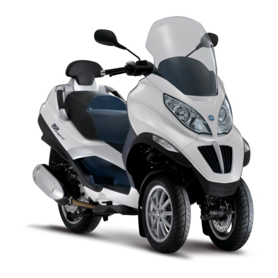
- Page 2 A hybrid is more than simply a vehicle with two powerplants Hybrid is a drive system integrating the advantages of two different power sources in a single solution. MP3 hybrid: two scooters in one for safe, easy and fun total mobility.
- Page 3 WHY MP3 HYBRID? TRAFFIC The practicality and comfort of a scooter Unrivalled in its class, with three wheels and SAFETY triple disc brakes The advantages of hybrid technology ENVIRONMENT...
- Page 4 PIAGGIO MP3 HYBRID: FCS The world's first and only scooter with 1. The most advanced scooter on parallel hybrid technology, the world's first the market plug-in hybrid vehicle and the first hybrid with lithium batteries 2. The lowest fuel consumption in Up to 60 Km/litre * (145 mi/1.0 US gal)
- Page 5 INDEX 1. USING THE VEHICLE ………………………. page 6 4. PRE-DELIVERY PROCEDURE ………………….……. page 61 1.1 Using the system ……………….…. page 7 4.1 Before delivering the vehicle ……..…… page 62 1.2 Working principle …..page 12 4.2 Checking tightening torques ……………...…… page 66 1.3 System logic ………………...
-
Page 6: Using The Vehicle
USING THE VEHICLE 1.1 USING THE SYSTEM 1.2 WORKING PRINCIPLE 1.3 SYSTEM LOGIC 1.4 SYSTEM COMPONENTS... -
Page 7: Using The System
1.1 USING THE SYSTEM Operating modes State of battery displayed on instrument charge panel LCD The 4 modes are selectable with the “HY TECH” button on the right hand handlebar switchgear set Traction battery energy is used (improved a) Hybrid Power performance and economy and reduced consumption and emissions) b) Hybrid Charge... - Page 8 At KEY-ON, the last mode selected is displayed: - if the vehicle was switched off in one of the two hybrid modes, at the subsequent key-on, the same hybrid mode is preselected and indicated on the display panel, with the relative message indicated constantly; - if the vehicle was switched off in electric mode, at the subsequent key-on, the same electric mode is preselected and indicated on the display panel with the relative flashing message.
- Page 9 Indicate the different operating modes Indicates no Indicates that the mains charging plug communication has been removed from its housing. between the traction The vehicle cannot be started in this battery ECU and the state as it is in mains charging mode! Kuadro ECU.
- Page 10 When the traction battery charge level approaches 0%, the charging indicator light (1), located at the centre of the handlebar cover, starts flashing. This means that the vehicle must be recharged from the mains or, should this not be possible, that HYBRID CHARGE mode must be selected.
- Page 11 To charge from the mains, lift the saddle and remove the charging plug(3), twisting slightly anticlockwise. This vehicle is equipped with the plug type required by currently applicable legislation for charging from public charging stations. charge from household mains (220/110V), use the adaptor supplied. A full charging cycle from the mains takes approximately 3 hours.
-
Page 12: Working Principle
1.2 WORKING PRINCIPLE “Hybrid” is a drive system integrating the advantages of two different powerplants in a single solution: 1. Petrol engine 2. Electric motor The two different power sources are used synergically and simultaneously (= in parallel) in an integrated system with management strategies and logic optimised to use each powerplant in the most efficient conditions. - Page 13 HYBRID POWER MODE At constant speed: the electric motor drives the rear wheel in parallel with the petrol engine, adding up to 15 Nm of torque (rated) to the driven pulley at low engine speeds.Up to 7,000 rpm (approx. 60 Km/h), the electric motor adds up to 2.5 kW to the power produced by the petrol engine.
- Page 14 Under deceleration: (braking or closed throttle), the electric motor recovers kinetic energy and uses it to charge the traction battery; when it functions as a generator, the electric motor produces a negative torque contribution equating to a braking power of 1.5 kW.
- Page 15 At speeds above 20 Km/h (12.5 mph), only Hybrid Power and Hybrid Charge modes are selectable from the instrument panel; under 20 Km/h (12.5 mph) and with the throttle grip released, electric mode may also be displayed and selected, to turn off the petrol engine and switch automatically from Hybrid mode to Electric mode (meaning that the vehicle can be ridden in areas restricted to...
- Page 16 HYBRID CHARGE MODE In addition to providing torque for traction, the petrol engine also charges the battery when travelling at constant speed. The electric motor functions as a generator, producing a negative torque contribution. The electric motor only contributes to powering the vehicle at speeds up to 30 Km/h (18.6 mph).
- Page 17 ELECTRIC MODE The electric motor drives the rear wheel, enabling top speed of 30 Km/h (18.6 mph) and a range of approximately 20 Km (12.42 mi). Power in electric mode comes from the energy stored in the traction battery. As a result, maximum range is only possible with a fully charged battery.
- Page 18 In Electric mode, the MP3 may only be ridden with the parallelogram unlocked; the hold system control electronics command the automatic release of the parallelogram lock once a given throttle control aperture is exceeded and according to the normal hold system logic.
- Page 19 ELECTRIC REVERSE MODE Reverse mode is only selectable if the vehicle is stationary. When in reverse mode, the control electronics sound the warning buzzer when a certain percentage throttle grip aperture is exceeded. The electric motor functions as a normal motor, but produces negative torque, driving the vehicle in reverse.
-
Page 20: System Logic
1.3 SYSTEM LOGIC System Architecture The 4 node star configuration CAN network interfaces the 4 ECUs on board of the vehicle: 1. KUADRO - VMS Vehicle Management System: Master ECU Location of 2. KUBO - Ride by Wire petrol engine ECUs in management: vehicle... - Page 21 Logic for switching from hybrid modes to pure electric modes In “Electric” mode, the system is capable of responding to the torque request from the rider at point 5 in the following list. 1. Pure electric mode selected and confirmed via the Hy-Tech button and input received by Kuadro (VMS).
- Page 22 RECOVERY MODE MEASURES In the event of malfunction of one or more of the vehicle management system devices, the Kuadro control unit informs the Kubo, control unit via the CAN line, requesting activation of the engine fault warning light. Depending on the type of fault or recovery mode implemented, the warning light may be lit constantly or flashing, according to the following criteria.
-
Page 23: System Components
1.4 SYSTEM COMPONENTS Electric motor Brushless, alternating current motor consisting of: 1. Permanent magnet rotor; 2. Stator; Position and speed sensor, consisting of: Rotor; - Fixed part; 125/300 cc Power output when operating as motor: 2.6 kW. Max. torque: 15Nm. Max. power output when operating as generator: 1.5 kW. Power supply voltage: 400 Volt AC. - Page 24 Lithium ion battery Safety switch button and Rated voltage 37 V Positive pole + relative indicator LED Rated capacity 31 Ah Rated energy storage 1.2 kWh Rated discharge current 60 A Peak discharge current 100 A for 30 s Rated charge current 30 A Peak charge current 80 A for 30 s...
- Page 25 The helmet compartment must be removed to access to the batteries. The BMS acts as insulation between the 12 V ground (services) and the 37 V ground (traction) To arm the traction battery (37V), press and hold the button for approximately 1 second.
- Page 26 BMS FUNCTIONS (the Kuadro ECU communicates with the BMS ECU via the CAN bus The battery control electronics carry out the following functions: Overvoltage protection; Undervoltage protection; Overcurrent protection; Overheat protection; Calculating state of charge (SOC); Calculating cell balancing; Driving the safety switch; Double protection fuse;...
- Page 27 The battery control electronics have the following functions: Charge current and voltage request Maximum charge current and voltage indication Maximum discharge current indication Three safety levels: “Warning “Alarm” Opening the safety switch...
-
Page 28: Technical Data
TECHNICAL DATA 2.1 VEHICLE SPECIFICATIONS 2.2 MAINTENANCE SCHEDULE 2.3 PRODUCTS... - Page 29 2.1 VEHICLE SPECIFICATIONS PETROL ENGINE SPECIFICATIONS 125 cc 300 cc TYPE Single cylinder 4-stroke Single cylinder 4-stroke ENGINE CAPACITY 124 cm 278 cm IDLE SPEED 1600 +/-100 rpm 1700 +/-100 rpm MAX POWER 11.0 kW at 8500 rpm 18.2 kW at 7500 rpm MAX TORQUE 16.0 kW at 3000 rpm 27.5 Nm at 3500 rpm...
-
Page 30: Electric Motor Specifications
ELECTRIC MOTOR SPECIFICATIONS 125/300 cc Three phase alternating current BRUSHLESS permanent magnet motor. Power output when operating as motor: 2.6 kW. ELECTRIC MOTOR Max. torque: 15Nm. Max. power output when operating as generator: 1.5 Power supply voltage: 400 Volt AC. -
Page 31: Vehicle Specifications
VEHICLE SPECIFICATIONS 125/300 cc Dual 240 mm hydraulic disc brakes operated FRONT BRAKE from right hand lever on handlebar Single 240 mm hydraulic disc brake operated REAR BRAKE from left hand lever on handlebar All three disc brakes operated simultaneously INTEGRAL BRAKING SYSTEM from pedal on footrest platform. -
Page 32: Maintenance Schedule
2.2 MAINTENANCE SCHEDULE TABLE Km x 1,000 Roller bearing - Driven pulley Safety locks Spark plug Driving belt Throttle control Air filter Oil filter CVT filter Valve clearance Electrical system and battery Brake lever Brake fluid * Coolant* Engine oil Hub oil I: CHECK, CLEAN AND ADJUST, LUBRICATE OR REPLACE IF NECESSARY C: CLEAN, R: REPLACE, A: ADJUST, L: LUBRICATE * Replace every 2 years - At each service, check for updates for the software in each ECU... - Page 33 TABLE Km x 1,000 Headlight aiming Brake pads CVT sliders / rollers Tyre pressure and wear Test ride Radiator (external cleaning) Suspension Steering Roll lock calliper control cable Cables I: CHECK, CLEAN AND ADJUST, LUBRICATE OR REPLACE IF NECESSARY C: CLEAN, R: REPLACE, A: ADJUST, L: LUBRICATE * Replace every 2 years - At each service, check for updates for the software in each ECU IF THE VEHICLE IS USED IN PARTICULARLY DUSTY CONDITIONS, THE MAINTENANCE INTERVALS FOR THE AIR FILTER AND CVT FILTER MUST BE SHORTENED TO...
-
Page 34: Specifications
2.3 PRODUCTS TABLE OF RECOMMENDED PRODUCTS PRODUCT DESCRIPTION SPECIFICATIONS QUANTITY SAE 80W-90, API GL-4 Transmission oil AGIP GEAR 80W-90 250 cm multigrade mineral oil 1.3 lt.(0.34 US gal) (complete SAE 5W-40 synthetic fill) AGIP CITY HI TEC 4T Engine oil oil, API SL, ACEA A3, 1.2 lt.(0.31 US JASO MA... - Page 35 3.1 NAVIGATOR 3.2 PGDS 3.3 BMS...
- Page 36 Diagnosis Tool Navigator is the fundamental tool used for the static and dynamic testing of all Piaggio vehicle electronic systems. The lowest recommended firmware version for using the diagnostic environment is 1.0.7.5 (required for reprogramming the BMS of the MP3 Hybrid)
- Page 37 PGDS PIAGGIO GROUP DIAGNOSTIC SOFTWARE PGDS is currently the best software solution for use with the Navigator diagnostic interface. The minimum recommended software version for using the diagnostic environment is 8.0.1...
- Page 38 Diagnosing the KUADRO Electric Management System ECU INFO Drawing number 00641231 Hardware version number H0001203 Hardware version number Software version number P7PH1D-0300 Mapping 0208A006 (usually the reference INFO for calibration updates) Type-approval code KUAD07 ISO code 35 12 87 41 33 Author of last programming DNX8T0000123 (Navigator if ripped by dealer) Reprogramming or production...
- Page 39 Diagnosing the KUADRO Electric Management System PARAMETERS Electric Motor Speed Value which may be positive or negative (in reverse mode): from -1000 to +13500 () Three-phase bridge temperature °C Value measured by internal sensor in ECU: from - 5° to + 80° (raw signal) High voltage bridge temperature °C Value measured by internal sensor in ECU: from - 5°...
- Page 40 Diagnosing the KUADRO Electric Management System STATES Electric motor phase synchronisation Phase set/Phase not set On/Off Mains charging switch Closed/Open Kuadro cooling fan On/Off Mains charging indicator On/Off Enable DC/DC On/Off Buzzer On/Off Battery current dependent limiting Remark 1 Battery voltage dependent limiting Remark 2 SOC dependent limiting Remark 3...
- Page 41 Diagnosing the KUADRO Electric Management System STATES Remark Value varying from 1 -> 0 (Total torque limiting) 0.01-0.25 (Very severe torque limiting) 0.26-0.50 (Severe torque limiting) 0.51-0.79 (Torque limiting) 0.80-0.99 (Moderate torque limiting) 1 No torque limiting Remark Value varying from 0 to 1 -> 0 (Total torque limiting) 0.01-0.25 (Very severe torque limiting) 0.26-0.50 (Severe torque limiting) 0.51-0.79 (Torque limiting) 0.80-0.99 (Moderate torque limiting) 1 No torque limiting Remark Value varying from 0 to 1 ->...
- Page 42 Diagnosing the KUADRO Electric Management System ACTIVATION 1 Error clearing Perform this operation after rectifying the fault Used to ascertain whether the KUADRO is capable of managing the buzzer 2 Buzzer autonomously, such as when in electric reverse mode, for example Bear in mind that this indicator is also used by the KUADRO to indicate when 3 Mains charging indicator battery limiting is active (it is important to check that this indicator is functioning...
- Page 43 Diagnosing the KUADRO Electric Management System SETTINGS Carry out in the case of replacing the Kuadro ECU - Reset motor phase electric motor – motor rotation sensor – or removal of synchronisation motor components. Resetting Electric Motor Phase Synchronisation 1. Place the vehicle on the centre stand, with the rear wheel free to turn 2.
- Page 44 Diagnosing the KUADRO Electric Management System AMBIENT PARAMETERS Electric Motor Speed Throttle aperture percentage Electric motor torque Operating mode Battery state of charge (SOC) Traction battery voltage Volt Electric motor temperature °C Kuadro ECU temperature °C...
- Page 45 Diagnosing the KUADRO Electric Management System ERRORS Safety 3 communication line (diagnosis of In the event of a fault, attempt reprogramming, then replace INVERTER if P0600 SPI communication line between DSP and necessary PPC) In the event of a fault, attempt reprogramming, then replace INVERTER if P0602 Internal communication line necessary...
- Page 46 Diagnosing the KUADRO Electric Management System ERRORS P0A05 Three-phase inverter temperature sensor If value not in range from -50° to + 200°, replace INVERTER 12V DC/DC converter enable command P0A11 Replace INVERTER feedback The sensor measures a voltage that varies in relation to the rotational position of the electric motor rotor.
- Page 47 Diagnosing the KUADRO Electric Management System ERRORS Current values range from 110A (with electric motor functioning as a motor) to -35A (with electric motor functioning as a generator). During mains charging, the value ranges from approx. – 16A to -24 A. Peak values P0A28 36 V battery pack current may indicatively reach 110 A, whereas the value is approximately 60 A...
- Page 48 Diagnosing the KUADRO Electric Management System ERRORS Power voltage circuit protection Check whether the traction battery is armed. If the battery is not armed, P0A37 hardware perform battery diagnosis. If the battery is armed, replace the inverter Hardware diagnosis on DSP generic Check phase sensor as described in SSM (motor rotation and phase P0A38 default...
- Page 49 Diagnosing the KUADRO Electric Management System ERRORS P1A00 Three-phase inverter direct current power Replace inverter P1A01 Clamp circuit Replace inverter P1A27 36 V battery pack voltage sensor Replace inverter P1A28 36 V battery pack current sensor Replace inverter Coherence between 36V battery pack P2A27 voltage sensor and battery management system ECU (BMS)
- Page 50 Diagnosing the KUADRO Electric Management System ERRORS The inverter fan power unit, located inside the Kuadro ECU, diagnosis an open circuit state with a voltage of zero or less than 8.5 V in the event of poor conductivity. This fault is diagnosed in the absence of the electric fan INT / P0481 Kuadro fan power unit diagnosis...
-
Page 51: Bms Interface
BMS INTERFACE The interface between the Navigator and the BMS (Battery Management System) consists of a specific cable (p/n 020878Y), connected between the male connector of the Navigator and the female 5-way connector on the BMS. -
Page 52: Vehicle Interface
VEHICLE INTERFACE The vehicle interface consists of the specific cable (p/n 020687Y), whereas the cable with p/n 020870Y is used as the KUBO ECU interface and the cable with p/n 020871Y is used as the KUADRO interface. - Page 53 BMS Battery Management System Diagnosis ECU info Indicates the manufacturer Producer Efi Technology Identifies whether cross-ECU compatibility (BMS-KUADRO-KUBO) is implemented in this software Compatibility HC8 Kernel Version HC8 Application Version ATMEL Kernel Version ATMEL Application Version ATMEL Calibration Battery Serial Number 1555 Encryption Yes/No...
- Page 54 BMS Battery Management System Diagnosis PARAMETERS Value varying in relation to battery charge. 20% effective battery charge Effective battery state of corresponds to 0% on indicator. Do not use the vehicle at lower values. Cross- 20...100 % charge (SOC) check with multimeter, at 20% voltage should be approx. 35V Above 36.5 Volt, the indicator must show values above 0%.
- Page 55 BMS Battery Management System Diagnosis PARAMETERS Check that the current is <75 A in the red sector of the SOC indicator Maximum discharge current 0...100 A Check that the current is <50 A at a temp of -10°C<x<+55°C and an SOC >50% >75% current should be <30 A Maximum charge current 0...50 A...
- Page 56 BMS Battery Management System Diagnosis STATES Open RED LED, 1 flash every 5 sec Switch State Closed GREEN LED, 1 flash every 5 sec Switch aperture delay Not detected Cell balancing ERROR Detected Not active Cell Balancing Active No charging Charging State of charge Charge Complete...
- Page 57 BMS Battery Management System Diagnosis STATES Temperature too high for discharging alarm Voltage too high warning Voltage too high alarm Excessive discharge current warning Excessive discharge current alarm Excessive charge current warning Excessive charge current alarm Capacity too low Voltage too low Warning Voltage too low Alarm...
- Page 58 BMS Battery Management System Diagnosis STATES Air temperature Current Sensor fault Voltage Sensor fault Switch fault Internal fuse fault Vehicle stop request Internal communication error Temperature too high for charging warning Temperature too high for charging alarm...
- Page 59 BMS Battery Management System Diagnosis STATES Temperature too low for discharging warning Temperature too low for discharging Alarm Temperature too low for charging warning Temperature too low for charging Alarm...
- Page 60 C:\Programmi\Piaggiogroup\Bin\Bike\autodia\maps\save The .bin file, identifiable by the name of the battery manufacturer and serial number in the file name itself, can only be consulted by specialised Piaggio technical support personnel. (e.g.: EFi1234) the battery 1234 serial number is indicated on the battery barcode label.
- Page 61 BMS Battery Management System Diagnosis ERRORS A battery that disarms is a very strong indication that thorough checks are necessary. The battery stores the causes and conditions of the fault in its internal buffer memory when it disarms. The following table lists the possible errors viewable by opening the battery .bin file with the specific application FreezeFrameBMS.exe (supplied to specialised technical support personnel) and the respective battery faults.
- Page 62 BMS Battery Management System Diagnosis ERRORS Error DiagLine Description Error Codes Decoding Battery Change VOLTAGE_WARNING_CELL_1 Detailed diagnosis of the system VOLTAGE_ALARM_CELL_1 Detailed diagnosis of the system VOLTAGE_OPEN_CELL_1 Detailed diagnosis of the system TEMPERATURE_WARNING_CELL_1 1,2,3,4,5,6 Detailed diagnosis of the system TEMPERATURE_ALARM_CELL_1 1,2,3,4,5,6 Detailed diagnosis of the system TEMPERATURE_OPEN_CELL_1...
- Page 63 BMS Battery Management System Diagnosis ERRORS Error DiagLine Description Error Codes Decoding Battery Change TEMPERATURE_OPEN_CELL_3 1,2,3,4,5,6 Detailed diagnosis of the system VOLTAGE_WARNING_CELL_4 Detailed diagnosis of the system VOLTAGE_ALARM_CELL_4 Detailed diagnosis of the system VOLTAGE_OPEN_CELL_4 Detailed diagnosis of the system TEMPERATURE_WARNING_CELL_4 1,2,3,4,5,6 Detailed diagnosis of the system TEMPERATURE_ALARM_CELL_4...
- Page 64 BMS Battery Management System Diagnosis ERRORS Error DiagLine Description Error Codes Decoding Battery Change TEMPERATURE_OPEN_CELL_6 1,2,3,4,5,6 Detailed diagnosis of the system VOLTAGE_WARNING_CELL_7 Detailed diagnosis of the system VOLTAGE_ALARM_CELL_7 Detailed diagnosis of the system VOLTAGE_OPEN_CELL_7 Detailed diagnosis of the system TEMPERATURE_WARNING_CELL_7 1,2,3,4,5,6 Detailed diagnosis of the system TEMPERATURE_ALARM_CELL_7...
- Page 65 BMS Battery Management System Diagnosis ERRORS Error DiagLine Description Error Codes Decoding Battery Change VOLTAGE_OPEN_CELL_10 Detailed diagnosis of the system TEMPERATURE_WARNING_CELL_10 1,2,3,4,5,6 Detailed diagnosis of the system TEMPERATURE_ALARM_CELL_10 1,2,3,4,5,6 Detailed diagnosis of the system TEMPERATURE_OPEN_CELL_10 1,2,3,4,5,6 Detailed diagnosis of the system CURRENT_WARNING Detailed diagnosis of the system CURRENT_ALARM...
- Page 66 BMS Battery Management System Diagnosis ERRORS Error DiagLine Description Error Codes Decoding Battery Change HARDWARE_CHECK_CELL_1 1,2,3 HARDWARE_CHECK_CELL_2 1,2,3 HARDWARE_CHECK_CELL_3 1,2,3 HARDWARE_CHECK_CELL_4 1,2,3 HARDWARE_CHECK_CELL_5 1,2,3 HARDWARE_CHECK_CELL_6 1,2,3 HARDWARE_CHECK_CELL_7 1,2,3 HARDWARE_CHECK_CELL_8 1,2,3 HARDWARE_CHECK_CELL_9 1,2,3 HARDWARE_CHECK_CELL_10 1,2,3 HI_RES_CURRENT_CONGRUENCY LOW_RES_CURRENT_CONGRUENCY BLOWN_FUSE_FAILURE Detailed diagnosis of the system CHARGE_SWITCH_FAILURE DISCHARGE_SWITCH_FAILURE TEMPERATURE_CONGRUENCY...
- Page 67 VEHICLE PRE-DELIVERY PROCEDURE 4.1 BEFORE DELIVERING THE VEHICLE … 4.2 CHECKING TIGHTENING TORQUES 4.3 ELECTRICAL SYSTEM 4.4 CHECKING FLUID LEVELS 4.5 ROAD TEST 4.6 CHECKS AFTER ROAD TEST 4.7 FUNCTIONAL TEST 4.8 PHASE-SYNCHRONISING THE ELECTRIC MOTOR...
- Page 68 4.1 CARRY OUT THE FOLLOWING CHECKS BEFORE DELIVERING THE VEHICLE: Fit the plastic cover supplied onto the joint onto the steering tube as shown in the figure. Proceed as follows if the customer requests installation of splash guards on the vehicle: Fit the splash guard inside the mudguard as shown in the figure, aligning the 4 anchor holes...
- Page 69 Fit the 4 washers and the 4 screws on the outer side of the mudguard and tighten to a torque of 2 - 3 CHARGE THE TRACTION BATTERY FULLY BEFORE DELIVERING THE VEHICLE TO THE CUSTOMER. Activation procedure for traction battery: The LED on the battery flashes red (approx.
- Page 70 To charge from the mains, lift the saddle and remove the charging plug, twisting slightly anticlockwise. An adaptor must be used in order to charge from the household mains. This adapter is supplied with the vehicle and kept in the rear case. The power cable is fitted with a fused device “C”.
-
Page 71: Electrical Characteristics
During the pre-delivery procedure, after completing all the operations indicated, always remember to connect the Navigator and delete all the errors from all the ECUs and check that the ECU software is updated correctly (contact the Piaggio Help Desk for any queries): 1. Hold system 2. Kubo 3. - Page 72 4.2 CHECKING TIGHTENING TORQUES Visually check that there is a yellow mark on the following fastenings: FRONT SUSPENSION Front left/right wheel fastener screws Speed sensor fastener screw Screw fastening pipe union – roll lock calliper REAR SUSPENSION Upper and lower shock absorber fastener screws Screws fastening silencer mounting arm - engine Rear wheel axle nut FRONT BRAKE...
-
Page 73: Electrical System
4.3 ELECTRICAL SYSTEM Battery; Main switch Lights: high beam lights, low beam lights, taillights (front and rear) and relevant indicator lights; Adjusting headlight in accordance with applicable legislation; Front and rear brake light buttons and relative bulb; Turn indicators and relative indicator lights; Instrument panel light;... -
Page 74: Checking Fluid Levels
4.4 CHECKING FLUID LEVELS Hydraulic braking system fluid level; Roll lock system fluid level; Rear hub oil level; Engine coolant level; Engine oil level; 4.5 ROAD TEST Cold start; Instrument function; Response to throttle control; Stability under acceleration and braking; Function of front, rear and parking brake;... -
Page 75: Functional Test
4.6 STATIC TEST AFTER TEST RIDE Restart with engine warm; Idle speed stability (turning the handlebar); Uniform steering function; Leaks; Electric radiator fan function; 4.7 FUNCTIONAL TEST Hydraulic brake system: lever travel; Clutch: checking function; Engine: checking general function and for abnormal noise; Other: checking documents, chassis and engine number, tools and equipment, licence plate fitment, locks, tyre pressure, and fitment of rear view mirrors and any accessories specified. - Page 76 4.8 PHASE-SYNCHRONISING THE ELECTRIC MOTOR Resetting Electric Motor Phase Synchronisation Phase synchronisation is reset with the Navigator. Subsequently, the ECU obliges the user to perform a specific procedure to resynchronise the phases. Phase synchronisation reset procedure (Navigator): must be performed each time any of the following components is removed or replaced: 1.
- Page 77 Resetting Electric Motor Phase Synchronisation 1. Place the vehicle on the centre stand, with the rear wheel free to turn 2. From the PGDS settings, enable Reset phase synchronisation 3. Key OFF (Power latch) 4. Key ON 5. Ensure that the reset procedure has been performed correctly - there should be no state indication on the instrument panel display.
- Page 78 Synchronisation procedure: Forced by the ECU in the event of replacement: New Kuadro ECU (not synchronised). This procedure is managed entirely by the Kuadro ECU and may be monitored only with the Navigator. 1. Key ON 2. No state indication is shown on the instrument panel display. 3.
- Page 79 Synchronisation procedure: It is imperative that phase-synchronisation is carried out with the transmission at operating temperature (e.g.: after riding a few kilometres (5)), so that the final drive is correctly lubricated and to ensure that the electric motor is phase-synchronised more precisely. It is therefore advisable to ride a few kilometres after carrying out the phase- synchronisation procedure and then repeat the reset phase-synchronisation procedure with the Navigator.
- Page 80 5. ELECTRICAL CIRCUIT DIAGRAMS 5.1 INJECTION SYSTEM DIAGRAM 5.2 HOLD SYSTEM DIAGRAM 5.3 TRACTION SYSTEM DIAGRAM...
Need help?
Do you have a question about the MP3 Hybrid and is the answer not in the manual?
Questions and answers