Terex Genie Z-34/22 IC Operator's Manual
Hide thumbs
Also See for Genie Z-34/22 IC:
- Service and repair manual (133 pages) ,
- Maintenance manual (198 pages) ,
- Maintenance manual (192 pages)

Related Manuals for Terex Genie Z-34/22 IC


Summary of Contents for Terex Genie Z-34/22 IC
- Page 1 Operator's Manual Serial Number Range -34/22 IC ® from Z34F-14001 from Z34D-1900 with Maintenance Information Original Instructions Seventh Edition First Printing Part No. 1297940GT...
-
Page 2: Table Of Contents
Contents of EC Declaration of Conformity ..54 Copyright © 1996 Terex Corporation Seventh Edition: First Printing, February 2020 Genie and "Z" are registered trademarks of Terex South Dakota, Inc. in the U.S.A. and many other countries. Complies with EC Directive 2006/42/EC See EC Declaration of Conformity ®... -
Page 3: Introduction
Seventh Edition • First Printing Operator's Manual Introduction Introduction Intended Use and Familiarization Product Identification Guide The machine serial number is located on the serial label. The intended use of this machine is to lift personnel, including tools, and materials to an aerial work site. Serial number stamped Serial label Before operating the machine, it’s the operator’s... - Page 4 Operator's Manual Seventh Edition • First Printing Introduction Platform controls symbology and related Ground controls symbology and related machine movement: machine movement: Platform level swtich Platform level, jib boom up/down, primary boom extend/retract, primary boom Platform rotate switch up/down, and secondary boom retract/lower.
- Page 5 Seventh Edition • First Printing Operator's Manual Introduction Bulletin Distribution and Contacting the Manufacturer Compliance At times it may be necessary to contact Genie. When you do, be ready to supply the model Safety of product users is of paramount importance number and serial number of your machine, along to Genie.
- Page 6 Operator's Manual Seventh Edition • First Printing Introduction Danger Failure to obey the instructions and safety rules in this manual will result in death or serious injury. Do Not Operate Unless: You learn and practice the principles of safe machine operation contained in this operator’s manual.
- Page 7 Seventh Edition • First Printing Operator's Manual Introduction Safety Sign Maintenance Hazard Classification Replace any missing or damaged safety signs. Decals on this machine use symbols, color coding, Keep operator safety in mind at all times. Use mild and signal words to identify the following: soap and water to clean safety signs.
-
Page 8: Symbol And Hazard Pictorials Definitions
Operator's Manual Seventh Edition • First Printing Symbol and Hazard Pictorials Definitions Symbol and Hazard Pictorials Definitions Fire hazard Explosion hazard Explosion hazard Do not use ether or No smoking. other high energy No flame. starting aids on Stop engine. machines equipped with glow plugs. - Page 9 Seventh Edition • First Printing Operator's Manual Symbol and Hazard Pictorials Definitions Tie-down point Lifting point Platform tie-down Lifting & tie down Lanyard anchorage instructions instructions points Corrosive acid. Color coded direction Runaway hazard Collision hazard Collision hazard arrows Electrocution hazard Avoid contact Disconnect battery Voltage rating for...
-
Page 10: General Safety
Operator's Manual Seventh Edition • First Printing General Safety 114252 General Safety Z 3 4 2 2 -1 2 3 4 1263542 114249 114252 133067 ® -34/22 IC Part No. 1297940GT... - Page 11 Seventh Edition • First Printing Operator's Manual General Safety 82487 133067 114252 1263542 1286362 133067 114391 ® Part No. 1297940GT -34/22 IC...
- Page 12 Operator's Manual Seventh Edition • First Printing General Safety *219954 133067 *1299792 219958 114248 219956 1299438 82487 114252 82487 These decals are model, option or configuration specific. ® -34/22 IC Part No. 1297940GT...
-
Page 13: Personal Safety
Seventh Edition • First Printing Operator's Manual Personal Safety Personal Safety Personal Fall Protection Personal fall protection equipment (PFPE) is required when operating this machine. Occupants must wear a safety belt or harness in accordance with governmental regulations. Attach the lanyard to the anchor provided in the platform. Operators must comply with employer, job site and governmental rules regarding the use of personal protective equipment. -
Page 14: Work Area Safety
Operator's Manual Seventh Edition • First Printing Work Area Safety Work Area Safety Tip-over Hazards Electrocution Hazards Occupants, equipment and materials shall not This machine is not electrically insulated and will exceed the maximum platform capacity. not provide protection from contact with or proximity to electrical current. - Page 15 Seventh Edition • First Printing Operator's Manual Work Area Safety Do not depend on the tilt alarm as a level indicator. Do not alter or disable the limit switches. The tilt alarm sounds in the platform only when the Do not drive over 0.6 mph / 1 km/h with the primary machine is on a severe slope.
- Page 16 Operator's Manual Seventh Edition • First Printing Work Area Safety Do not modify or alter a mobile elevating work Use extreme care and platform without prior written permission from the slow speeds while driving manufacturer. Mounting attachments for holding the machine in the stowed tools or other materials onto the platform, position across uneven toeboards, or guard rail system can increase the...
- Page 17 Seventh Edition • First Printing Operator's Manual Work Area Safety Operation on Slopes Hazards Do not use the machine on a moving or mobile surface or vehicle. Do not drive the machine on a slope that exceeds the maximum uphill, downhill or side slope rating of Do not modify or alter a mobile elevating work the machine.
- Page 18 Operator's Manual Seventh Edition • First Printing Work Area Safety Fall Hazards Collision Hazards Occupants must wear a Be aware of limited sight safety belt or harness in distance and blind spots accordance with when driving or operating. governmental regulations. Attach the lanyard to the anchor provided in the Be aware of the boom position and tailswing when...
- Page 19 Seventh Edition • First Printing Operator's Manual Work Area Safety Bodily Injury Hazard Observe and use the color-coded direction arrows on the platform controls and drive chassis for drive Always operate the machine in a well-ventilated and steer functions. area to avoid carbon monoxide poisoning. Do not lower the boom Do not operate the machine with a hydraulic oil or unless the area below is...
- Page 20 Operator's Manual Seventh Edition • First Printing Work Area Safety Damaged Machine Hazards Battery Safety Do not use a damaged or malfunctioning machine. Burn Hazards Conduct a thorough pre-operation inspection of the Batteries contain acid. machine and test all functions before each work Always wear protective shift.
- Page 21 Seventh Edition • First Printing Operator's Manual Work Area Safety Contact Alarm Safety Lockout After Each Use Read, understand and obey all warnings and Select a safe parking location–firm level instructions provided with the contact alarm. surface, clear of obstruction and traffic. Retract and lower the boom to the stowed Be sure the contact alarm is securely installed.
-
Page 22: Legend
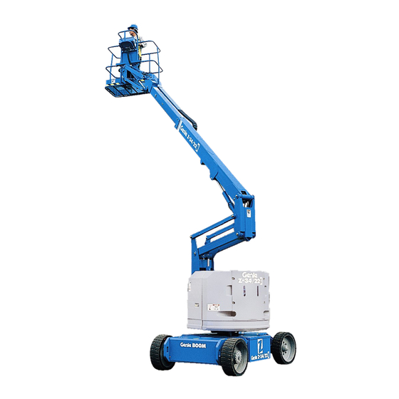
Operator's Manual Seventh Edition • First Printing Legend Legend Non-steer tire Platform controls Steer tire Platform Ground controls Lanyard anchorage points Secondary boom 10 Sliding mid-rail Primary boom 11 Manual storage container Jib boom 12 Foot switch ® -34/22 IC Part No. -
Page 23: Controls
Seventh Edition • First Printing Operator's Manual Controls Controls The ground control station is to be used as a means to raise the platform for storage purposes and for function tests. The ground control station can be used in the event of an emergency to rescue an incapacitated person in the platform. - Page 24 Operator's Manual Seventh Edition • First Printing Controls STOP DRIVE ENABLE OPERATION Light on indicates that boom has moved past a non-steer tire and drive function is turned off. To drive, hold drive enable switch up or down and slowly move drive control handle.
-
Page 25: Inspections
Seventh Edition • First Printing Operator's Manual Inspections Inspections Pre-operation Inspection Fundamentals It is the responsibility of the operator to perform a pre-operation inspection and routine maintenance. The pre-operation inspection is a visual inspection performed by the operator prior to each work shift. Do Not Operate Unless: The inspection is designed to discover if anything is apparently wrong with a machine before the... - Page 26 Operator's Manual Seventh Edition • First Printing Inspections Pre-operation Inspection Engine and related components Limit switches Be sure that the operator’s, safety and Contact alarm (if equipped) responsibilities manuals are complete, legible and in the storage container located in the ...
- Page 27 Seventh Edition • First Printing Operator's Manual Inspections Function Test Fundamentals The function tests are designed to discover any malfunctions before the machine is put into service. The operator must follow the step-by-step instructions to test all machine functions. A malfunctioning machine must never be used. If malfunctions are discovered, the machine must be Do Not Operate Unless: tagged and removed from service.
- Page 28 Operator's Manual Seventh Edition • First Printing Inspections At the Ground Controls Test the Tilt Sensor Select a test area that is firm, level and free of Turn the key switch to hazards. platform control. Pull out the platform red Emergency Turn the key switch to ground control.
- Page 29 Seventh Edition • First Printing Operator's Manual Inspections Test the Foot Switch At the Platform Controls 20 Push in the platform red Emergency Stop 14 Turn the key switch to platform control. button to the off position. 15 Pull out the red Emergency Stop button to the 21 Pull out the red Emergency Stop button to the on position.
- Page 30 Operator's Manual Seventh Edition • First Printing Inspections Test the Steering Test Drive and Braking 27 Press down the foot switch. 32 Press down the foot switch. 28 Press the thumb rocker switch on top of the 33 Slowly move the drive control handle in the control handle in the direction indicated by the direction indicated by the blue arrow on the blue triangle on the control panel.
- Page 31 Seventh Edition • First Printing Operator's Manual Inspections Test Limited Drive Speed Test the Drive Enable System 40 Press down the foot switch. 35 Press down the foot switch. 41 Raise the primary boom 1 foot/30 cm. 36 Retract the primary boom to the stowed position.
- Page 32 Operator's Manual Seventh Edition • First Printing Inspections 58 With the boom fully stowed, drive the machine Test Drive Tilt Cutout onto a slope where the chassis pitch angle is 49 Press down the foot switch. greater than 2.5°. 50 With the boom fully stowed, drive the machine Result: The machine should continue to drive.
- Page 33 Seventh Edition • First Printing Operator's Manual Inspections 66 Return to level ground and extend the primary Test Auxiliary Power boom approximately 1.6 ft / 0.5 m. 74 Shut the engine off. 67 Drive the machine onto a slope where the 75 Pull out the red Emergency Stop button to the chassis roll angle is greater than 4.5°.
- Page 34 Operator's Manual Seventh Edition • First Printing Inspections Test the Contact Alarm (if equipped) 86 Operate each machine function. 82 Do not activate the foot switch and press on Result: All machine functions should not the contact alarm cable to release the actuator operate.
- Page 35 Seventh Edition • First Printing Operator's Manual Inspections Workplace Inspection Checklist Be aware of and avoid the following hazardous situations: drop-offs or holes bumps, floor obstructions, or debris sloped surfaces Do Not Operate Unless: unstable or slippery surfaces ...
- Page 36 Operator's Manual Seventh Edition • First Printing Inspections Inspection for Decals with Part No. Decal Description Symbols 97815 Label — Lower Mid-rail 114248 Label — Tip-over Hazard, Tilt Alarm Determine whether the decals on your machine 114249 Label — Tip-over Hazard, Tires** have words or symbols.
- Page 37 Seventh Edition • First Printing Operator's Manual Inspections 133278 72094 28171 *28158 *28159 82487 114420 1298857 133067 114252 72086 37053 28160 52475 37056 114252 37055 1278982 1263542 1278542 Z4 50 6- 12 34 5 72086 52475 37056 **114249 37054 82487 **133299 72086 52475...
-
Page 38: Operating Instructions
Operator's Manual Seventh Edition • First Printing Operating Instructions Operating Instructions Fundamentals The Operating Instructions section provides instructions for each aspect of machine operation. It is the operator’s responsibility to follow all the safety rules and instructions in the operator’s, safety, and responsibilities manuals. - Page 39 Seventh Edition • First Printing Operator's Manual Operating Instructions Starting the Engine Emergency Stop At the ground controls, turn the key switch to Push in the red Emergency Stop button to the off the desired position. position at the ground controls or the platform controls to stop all machine functions and turn the Be sure both ground and platform control red engine off.
- Page 40 Operator's Manual Seventh Edition • First Printing Operating Instructions Operation from Ground Operation from Platform Turn the key switch to ground control. Turn the key switch to platform control. Pull out the red Emergency Stop button to the Pull out both ground and platform red on position.
- Page 41 Seventh Edition • First Printing Operator's Manual Operating Instructions To Drive Driving on a slope Press down the foot switch. Determine the uphill, downhill and side slope ratings for the machine and determine the slope Increase speed: Slowly move the control grade.
- Page 42 Operator's Manual Seventh Edition • First Printing Operating Instructions To determine the slope grade: Drive Enable Measure the slope with a digital inclinometer OR Light on indicates that the boom use the following procedure. has moved just past either non-steer wheel and the drive You will need: function has been interrupted.
- Page 43 Seventh Edition • First Printing Operator's Manual Operating Instructions Engine Idle Select (rpm) Machine Not Level Indicator Light Select engine idle (rpm) using the symbols on the If the tilt alarm sounds when the control panel. platform is raised, use extreme caution.
- Page 44 Operator's Manual Seventh Edition • First Printing Operating Instructions Tilt Sensor Activation Settings Aircraft Protection Package (if equipped) If the platform bumpers come into contact with Model Chassis Angle Chassis Angle (front aircraft components, the machine will shut down (side to side) to back) and no functions will operate.
- Page 45 Seventh Edition • First Printing Operator's Manual Operating Instructions Contact Alarm (if equipped) After Each Use The contact alarm is designed to alert ground Select a safe parking location–firm level personnel when an operator makes contact with surface, clear of obstruction and traffic. the platform control panel, interrupting boom Retract and lower the boom to the stowed movement, sounding an alarm and flashing...
-
Page 46: Transport And Lifting Instructions
Operator's Manual Seventh Edition • First Printing Transport and Lifting Instructions Transport and Lifting Instructions Be sure the turntable is secured with the turntable rotation lock before transporting. Be sure to unlock the turntable for operation. Do not drive the machine on a slope that exceeds the uphill, downhill or side slope rating. - Page 47 Seventh Edition • First Printing Operator's Manual Transport and Lifting Instructions Free-wheel Configuration for Securing to Truck or Trailer for Winching Transit Chock the wheels to prevent the machine from Always chock the machine wheels in preparation rolling. for transport. Turn the key switch to the off position and remove Release the the key before transporting.
- Page 48 Operator's Manual Seventh Edition • First Printing Transport and Lifting Instructions Securing the Platform Make sure the jib and platform are in the stowed position. Place a block under the edge of the platform beneath the platform entry. Secure the platform with a nylon strap placed over the platform mount near the platform rotator (see below).
- Page 49 Seventh Edition • First Printing Operator's Manual Transport and Lifting Instructions Lifting Instructions Fully lower and retract the boom. Fully lower the jib. Remove all loose items on the machine. Determine the center of gravity of your machine using the table and the picture on this page. Observe and Obey: Attach the rigging only to the designated lifting points on the machine.
-
Page 50: Maintenance
Operator's Manual Seventh Edition • First Printing Maintenance Maintenance Check the Hydraulic Oil Level Maintaining the hydraulic oil at the proper level is essential to machine operation. Improper hydraulic Observe and Obey: oil levels can damage hydraulic components. Daily checks allow the inspector to identify changes in oil ... - Page 51 Seventh Edition • First Printing Operator's Manual Maintenance Check the Engine Coolant Level Check the Engine Oil Level Maintaining the engine coolant at the proper level Maintaining the proper engine oil level is essential is essential to engine service life. Improper coolant to good engine performance and service life.
- Page 52 Operator's Manual Seventh Edition • First Printing Maintenance Check the Batteries Scheduled Maintenance Maintenance performed quarterly, annually and every two years must be completed by a person trained and qualified to perform maintenance on Proper battery condition is essential to good this machine according to the procedures found in machine performance and operational safety.
-
Page 53: Specifications
Seventh Edition • First Printing Operator's Manual Specifications Specifications Z-34/22 2WD Industrial and RT Tire size (foam filled only) 10-16.5 NHS Height, working maximum 40 ft 6 in 12.5 m Highest root mean square value of weighted acceleration to which the whole body is subjected does not exceed Height, platform maximum 34 ft 6 in 10.5 m... - Page 54 Operator's Manual Seventh Edition • First Printing Specifications Tire size (foam filled only) 10-16.5 NHS Z-34/22 4WD RT Height, working maximum 40 ft 6 in 12.5 m Weight (Machine weights vary with option configurations. See Height, platform maximum 34 ft 6 in 10.5 m serial label for specific machine weight.) Height, stowed maximum...
- Page 55 Seventh Edition • First Printing Operator's Manual Specifications Range of Motion Chart Max Height Max Reach 35 ft 10.6 m 0 ft 30 ft 9.1 m 5 ft 1.5 m 25 ft 7.6 m 10 ft 20 ft 6.1 m 15 ft 4.6 m 15 ft...
-
Page 56: Contents Of Ec Declaration Of Conformity
Operator's Manual Seventh Edition • First Printing Contents of EC Declaration of Conformity Contents of EC Declaration of Conformity <Manufacturer’s name> hereby declares that the machinery described below complies with the provisions of the following Directives: 1. EC Directive 2006/42/EC, Machinery Directive, under consideration of harmonized European standard EN280 as described in EC type-examination certificate <variable field>...
Need help?
Do you have a question about the Genie Z-34/22 IC and is the answer not in the manual?
Questions and answers