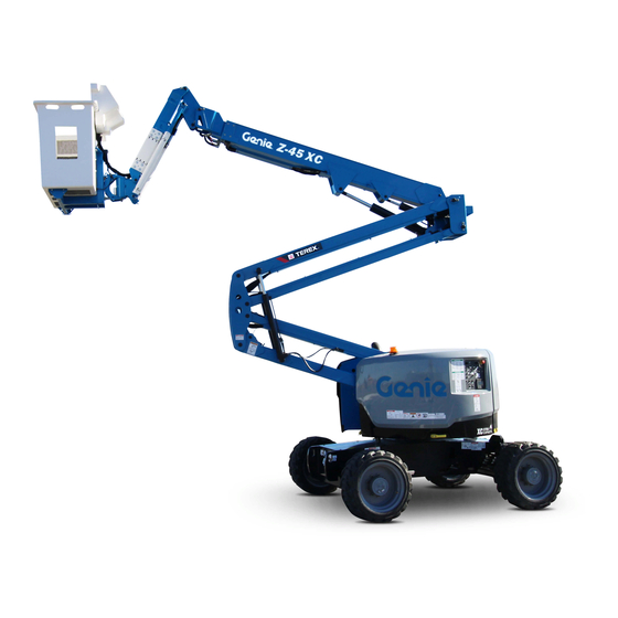
Terex Genie Z-45 XC Service And Repair Manual
Hide thumbs
Also See for Genie Z-45 XC:
- Operator's manual (80 pages) ,
- Operator's manual supplement (17 pages) ,
- Operator's manual supplement (10 pages)
Table of Contents
Advertisement
Service and Repair Manual
Z
-45 XC
®
Z
-45 HF
®
Serial Number Range
from Z4525XCF-101
from Z4525XCM-101
This manual includes:
Repair procedures
Fault Codes
Electrical and
Hydraulic Schematics
For detailed maintenance
procedures, refer to the
appropriate Maintenance
Manual for your machine.
Part No. 1268197GT
Rev E
November 2020
Advertisement
Table of Contents

Related Manuals for Terex Genie Z-45 XC


Summary of Contents for Terex Genie Z-45 XC
- Page 1 Service and Repair Manual Serial Number Range -45 XC from Z4525XCF-101 ® This manual includes: from Z4525XCM-101 Repair procedures -45 HF ® Fault Codes Electrical and Hydraulic Schematics For detailed maintenance procedures, refer to the appropriate Maintenance Manual for your machine. Part No.
-
Page 2: Find A Manual For This Model
Copyright © 2017 by Terex Corporation 1268197GT Rev E, November 2020 First Edition, Fifth Printing Genie and "Z" are registered trademarks of Terex South Dakota, Inc. in the U.S.A. and many other countries. "XC" is a trademark of Terex South Dakota, Inc. - Page 3 November 2020 Service and Repair Manual Introduction Revision History Revision Date Section Procedure / Page / Description 5/2017 Initial Release 8/2017 Fault Codes Control System Fault Codes Specifications Hydraulic Component Specifications Repair Function Manifold Components Schematics Hydraulic Schematic, 9/2017 Repair Procedure 2-3, 2-4 Fault Codes Introduction, Control System and Platform Overload Fault...
-
Page 4: Safety Rules
Service and Repair Manual November 2020 Safety Rules Section 1 Safety R ules Danger Failure to obey the instructions and safety rules in this manual and the appropriate Operator's Manual on your machine will result in death or serious injury. Many of the hazards identified in the operator's manual are also safety hazards when maintenance and repair procedures are... - Page 5 November 2020 Service and Repair Manual Safety Rules Personal Safety Workplace Safety Any person working on or around a machine must Any person working on or around a machine must be aware of all known safety hazards. Personal be aware of all known safety hazards. Personal safety and the continued safe operation of the safety and the continued safe operation of the machine should be your top priority.
-
Page 6: Table Of Contents
November 2020 Table of Contents Introduction Introduction ..................... ii Important Information ................. ii Find a Manual for this Model ..............ii Revision History ..................iii Section 1 Safety Rules .................... iv General Safety Rules ................iv Section 2 Specifications ..................1 Machine Specifications ................ - Page 7 November 2020 Table of Contents Section 3 Repair Procedures ................17 Introduction ....................17 Platform Controls .................. 19 1-1 ALC-500 Circuit Board ..............19 1-2 Joysticks .................... 20 How to Adjust the Joystick Max-out Setting ........20 How to Adjust the Joystick Ramp Rate Setting ......... 21 How to Adjust the Joystick Threshold Setting ........
- Page 8 November 2020 Table of Contents Engines ....................47 6-1 RPM Adjustment - Deutz D2011L03i Models ........47 6-2 RPM Adjustment - Perkins 404D-22 Models ........47 6-3 Flex Plate ..................47 How to Install the Flex Plate .............. 49 How to install the Pump and Bell Housing Assembly ......50 5-4 Engine Fault Codes ................
- Page 9 November 2020 Table of Contents Section 4 Fault Codes .................... 79 Introduction ....................79 Control System Fault Codes ..............80 How to Retrieve Control System Fault Codes ........80 Control System Fault Codes .............. 81 How to Retrieve Platform Overload System Fault Codes - Deutz D2011L03i, Perkins 404D-22 and Ford MSG-425 Models ..................
- Page 10 November 2020 Table of Contents Section 5 Schematics ..................123 Introduction ................... 123 Electrical Symbol Legend ..............124 Hydraulic Symbols Legend ..............125 Limit Switch Location Legend ............... 126 Electrical Component and Wire Color Legends ........127 Hour Meter Legend ................130 Electrical Schematics .................
- Page 11 November 2020 Table of Contents Ground Control Box Switch Panel Wiring Diagram, Deutz D2011L03i and Perkins 404D-22 - ANSI / CSA ....158 Ground Control Box Terminal Strip Wiring Diagram, Deutz D2011L03i and Perkins 404D-22 - ANSI / CSA ....159 Ground Control Box Switch Panel Wiring Diagram, Deutz D 2.9 L4 and Perkins 404F-E22T - ANSI / CSA ....
- Page 12 Service and Repair Manual November 2020 This page intentionally left blank. ™ • Z ® ® -45 XC -45 HF Part No. 1268197GT...
-
Page 13: Specifications
November 2020 Service and Repair Manual Specifications Section 2 Specific ati ons Machine Specifications Fuel capacities LPG tank 33.5 pounds Tires and wheels rough terrain 15,2 kg Tire size 315/55 D20 Fuel tank 17 gallons 64,4 liters Tire ply rating Hydraulic tank 22 gallons Tire weight, new foam filled... -
Page 14: Performance Specifications
Service and Repair Manual November 2020 Specifications Performance Specifications Hydraulic Oil Specifications Drive speed, maximum Hydraulic Fluid Specifications Stowed position 4.5 mph Genie specifications require hydraulic oils which are 7,2 km/h designed to give maximum protection to hydraulic systems, have the ability to perform over a wide 40 ft / 6.1 sec temperature range, and the viscosity index should 12,2 m / 6,1 sec... - Page 15 November 2020 Service and Repair Manual Specifications Chevron Rando HD Premium Oil Do not top off with incompatible hydraulic fluids. Hydraulic fluids MV Fluid Properties may be incompatible due to the differences in base additive ISO Grade chemistry. When incompatible Viscosity index fluids are mixed, insoluble materials may form and deposit...
- Page 16 Service and Repair Manual November 2020 Specifications Chevron 5606A Hydraulic Oil Petro-Canada Environ MV 46 Fluid Properties Fluid Properties ISO Grade ISO Grade Viscosity index Viscosity index Kinematic Viscosity Kinematic Viscosity cSt @ 200°F / 100°C cSt @ 200°F / 100°C cSt @ 104°F / 40°C 44.4 cSt @ 104°F / 40°C...
-
Page 17: Hydraulic Component Specifications
November 2020 Service and Repair Manual Specifications UCON Hydrolube HP-5046 Fluid Hydraulic Component Properties Specifications ISO Grade Drive Pump Viscosity index Type: bi-directional variable displacement piston pump Kinematic Viscosity Flow rate @ 2500 psi / 172 bar 32 gpm cSt @ 149°F / 65°C 121 L/min cSt @ 104°F / 40°C Drive pressure, maximum... - Page 18 Service and Repair Manual November 2020 Specifications Function manifold Manifold Component Specifications System relief valve pressure, 3200 psi Plug torque maximum 220,6 bar SAE No. 2 36 in-lbs / 4 Nm Secondary boom down relief 2100 psi SAE No. 4 10 ft-lbs / 13 Nm valve pressure 145 bar...
-
Page 19: Deutz D 2.9 L4 Engine Specifications
November 2020 Service and Repair Manual Specifications Deutz D2.9 L4 Engine Engine coolant Capacity 10 quarts Displacement 177 cu in 9,4 liters 2,9 liters Fuel injection system Number of cylinders Injection pump make Bosch Bore and Stroke 3.6 x 4.3 inches Injection pump pressure, 15000 psi 92 x 110 mm... -
Page 20: Deutz Td 2.2 L3 Engine Specifications
Service and Repair Manual November 2020 Specifications Deutz TD 2.2 L3 Engine Oil temperature switch Installation torque 8 - 18 ft-lbs Displacement 134 cu. in 11 - 24 Nm 2,2 liters Temperature switch point 257°F Number of cylinders 125°C Bore and Stroke 3.6 x 4.3 inches Oil Pressure switch 92 x 110 mm... -
Page 21: Deutz D2011 L03I Engine Specifications
November 2020 Service and Repair Manual Specifications Deutz D2011 L03i Engine Oil temperature switch Temperature switch point 300°F Displacement 142 cu in 149°C 2,33 liters Oil Pressure switch Number of cylinders Oil pressure switch point 22 psi Bore and Stroke 3.7 x 4.4 inches 1,5 bar 94 x 112 mm... -
Page 22: Perkins 404D-22 Engine Specifications
Service and Repair Manual November 2020 Specifications Perkins 404D-22 Engine Oil pressure sending unit Oil pressure switch point 14.2 psi Displacement 134 cu in 1 bar 2,2 liters Fuel injection system Number of cylinders Injection pump make Zexel Bore and Stroke 3.31 x 3.94 inches Injection pressure 2133 psi... -
Page 23: Perkins 404F-E22T Engine Specifications
November 2020 Service and Repair Manual Specifications Perkins 404F-E22T Engine Fuel injection system Injection pump make Zexel Displacement 134 cu in Injection pressure 2133 psi 2,2 liters 147 bar Number of cylinders Fuel requirement Bore and Stroke 3.31 x 3.94 inches For fuel requirements, refer to the engine Operator 84 x 100 mm Manual for your engine. -
Page 24: Ford Msg-425 Efi Engine Specifications
Service and Repair Manual November 2020 Specifications Ford MSG-425 EFI Engine Fuel requirement For fuel requirements, refer to the engine Operator Displacement 153 cu in Manual for your engine. 2,5 liters Ignition system Number of cylinders Spark plug type Motorcraft AYFS-32Y-R Bore and Stroke 3.5 x 3.9 inches Spark plug gap... -
Page 25: Machine Torque Specifications
November 2020 Service and Repair Manual Specifications Machine Torque Specifications JIC 37° Fittings (swivel nut or hose connection) Note: All torque values are shown lubricated SAE Dash Size Thread Size Flats unless otherwise noted. 7/16-20 Platform Rotator 9/16-18 1 1/2 1-8 center bolt, GR 5 483 ft-lbs 3/4-16... - Page 26 Service and Repair Manual November 2020 Specifications SAE O-ring Boss Port (tube fitting - installed into Aluminum) (all types) SAE Dash Size Torque 14 ft-lbs / 19 Nm 23 ft-lbs / 31,2 Nm 36 ft-lbs / 49 Nm 62 ft-lbs / 84 Nm 84 ft-lbs / 114 Nm 125 ft-lbs / 169,5 Nm 151 ft-lbs / 204,7 Nm...
-
Page 27: Torque Procedure
November 2020 Service and Repair Manual Specifications Torque Procedure Seal-Lok™ fittings Replace the O-ring. The O-ring must be replaced anytime the seal has been broken. The O-ring cannot be re-used if the fitting or hose end has been tightened beyond finger tight. - Page 28 Service and Repair Manual November 2020 Specifications Working clockwise on the body hex fitting, JIC 37° fittings make a second mark with a permanent ink marker to indicate the proper tightening Align the tube flare (hex nut) against the nose position.
-
Page 29: Repair Procedures
November 2020 Service and Repair Manual Repair Procedures Section 3 Repair Pr oc edures Machine Configuration: Unless otherwise specified, perform each repair procedure with the machine in the following configuration: Machine parked on a firm, level surface Key switch in the off position with the key Observe and Obey: removed ... - Page 30 Service and Repair Manual November 2020 Repair Procedures About This Section Most of the procedures in this section should only be performed by trained service professional in a suitably equipped workshop. Select the appropriate repair procedure after troubleshooting the problem. Perform disassembly procedures to the point where repairs can be completed.
-
Page 31: Platform Controls
November 2020 Service and Repair Manual Platform Controls Platform Controls ALC-500 Circuit Board The platform control box contains one printed circuit board. The ALC-500 circuit board inside the Note: When the ALC-500 circuit board is replaced, platform control box controls all proportional the joystick controllers will need to be calibrated. -
Page 32: Joysticks
Service and Repair Manual November 2020 Platform Controls How to Adj ust the Joystic k Max- out Setting How to Adjust the Joystick Max- Joysticks out Setting The max-out setting of a joystick controls the maximum speed of a joystick-controlled machine How to Calibrate a Joystick function. -
Page 33: How To Adjust The Joystick Ramp Rate Setting
November 2020 Service and Repair Manual Platform Controls How to Adj ust the Joystic k Ramp R ate Setting How to Adjust the Joystick Ramp Start the engine from the platform controls and press down the foot switch. Rate Setting Start a timer and activate the machine The ramp rate setting of a joystick controls the function that needs to be adjusted. - Page 34 Service and Repair Manual November 2020 Platform Controls Start the engine from the platform controls 13 Return the joystick to the neutral position and and press down the foot switch. wait for approximately 10 seconds to allow the settings to be saved. Start a timer and simultaneously move the joystick in either direction full stroke.
-
Page 35: How To Adjust The Joystick Threshold Setting
November 2020 Service and Repair Manual Platform Controls How to Adj ust the Joystic k Thr es hol d Setting How to Adjust the Joystick Select a boom function joystick to set the threshold. Threshold Setting 10 Slowly move the joystick off center in either The threshold setting of a joystick is the minimum direction just until the function begins to output at which a function proportional valve can... -
Page 36: Platform Components
Service and Repair Manual November 2020 Platform Components Tag, disconnect and plug the hydraulic hoses from the slave cylinder at the unions and Platform Leveling Slave Cylinder connect them together using a connector. Connect the hoses from the cylinder together The slave cylinder and the rotator pivot are the two using a connector. -
Page 37: How To Bleed The Slave Cylinder
November 2020 Service and Repair Manual Platform Components How to Bleed the Sl ave C ylinder How to Bleed the Slave Cylinder Platform Rotator Note: This procedure will have to be preformed outside. How to Bleed the Platform Raise the jib to a horizontal postion and raise the secondary boom 3 feet. -
Page 38: Platform Overload System
Service and Repair Manual November 2020 Platform Components Move the function enable toggle switch to either side and hold the platform rotate toggle Platform Overload System switch to the right position until the platform is fully rotated to the right. Continue holding the Proper calibration of the platform overload system toggle switch until air stops coming out of the is essential to safe machine operation. - Page 39 November 2020 Service and Repair Manual Platform Components Pull out the red Emergency Stop button and How to Perform a Full Load momentarily activate the calibration toggle Platform Calibration switch located on the left side of the control box in the up position 3 times to enter Perform this procedure if the platform support or calibration mode.
- Page 40 Service and Repair Manual November 2020 Platform Components XC models: Add maximum rated load of Activate and hold the calibration toggle switch 1000 lbs / 454 kg to the center of the platform. in the up position for 2 seconds to store the rated load calibration.
-
Page 41: How To Replace The Platform Overload Load Cell
November 2020 Service and Repair Manual Platform Components How to R eplac e the Platfor m Overload Load C ell How to Replace the Load Cell Sensor Platform Overload Recovery Fault Note: The preload adjustment should only be performed after the load cell sensor has been If the ground controls hour meter displays fault replaced. -
Page 42: Jib Boom Components
Service and Repair Manual November 2020 Jib Boom Components Remove the pin retaining fasteners from both platform rotator pivot pins. Do not remove the Jib Boom pins. Use a soft metal drift to remove the leveling How to Remove the Jib Boom arm pivot pin and let the leveling arms hang down. -
Page 43: Jib Boom Lift Cylinder
November 2020 Service and Repair Manual Jib Boom Components 15 Use a soft metal drift to remove the pin and let the cylinder hang down. Remove the platform Jib Boom Lift Cylinder rotator from the machine. Crushing hazard. The jib boom How to Remove the Jib Boom Lift could fall when the barrel-end Cylinder... - Page 44 Service and Repair Manual November 2020 Jib Boom Components Use a soft metal drift to tap the jib boom lift cylinder rod-end pivot pin half way out. Then lower one of the leveling arms to the ground. Tap the pin the other direction and lower the opposite leveling arm.
-
Page 45: Primary Boom Components
November 2020 Service and Repair Manual Primary Boom Components Tag, disconnect and plug the hydraulic hoses from the "V1" and "V2" ports on the Cable Track counterbalance valve manifold located on the platform rotator. Cap the fittings on the The primary boom cable track guides the cables manifold. - Page 46 Service and Repair Manual November 2020 Primary Boom Components Tag, disconnect and plug the platform rotator 16 Remove the pin retaining fasteners from the hydraulic hoses at the union located above primary boom lift cylinder rod-end pivot pin. the primary boom lift cylinder. Cap the fittings Do not remove the pin.
-
Page 47: How To Repair The Primary Boom Cable Track
November 2020 Service and Repair Manual Primary Boom Components How to R epair the Primar y Boom C abl e Tr ac k How to Repair the Primary Boom Cable Track Primary Boom Component damage hazard. How to Remove the Primary The boom cable track can be damaged if it is twisted. - Page 48 Service and Repair Manual November 2020 Primary Boom Components Remove the pin retaining fastener from the 14 Attach a 5 ton / 5,000 kg overhead crane to master cylinder barrel-end pivot pin. Use a the center point of the primary boom. soft metal drift to remove the pin.
-
Page 49: How To Disassemble The Primary Boom
November 2020 Service and Repair Manual Primary Boom Components How to Dis ass embl e the Primar y Boom How to Disassemble the Primary Remove the external snap rings from the extension cylinder rod-end pivot pins at the Boom platform end of the extension tube. Use a soft metal drift to remove the pins. -
Page 50: Primary Boom Lift Cylinder
Service and Repair Manual November 2020 Primary Boom Components Tag, disconnect and plug the primary boom lift cylinder hydraulic hoses. Cap the fittings Primary Boom Lift Cylinder on the cylinder. The primary boom lift cylinder raises and lowers Bodily injury hazard. Spraying the primary boom. -
Page 51: Primary Boom Extension Cylinder
November 2020 Service and Repair Manual Primary Boom Components Tag, disconnect and plug the primary boom extension cylinder hydraulic hoses. Cap the Primary Boom Extension fittings on the cylinder. Cylinder Bodily injury hazard. Spraying hydraulic oil can penetrate and The primary boom extension cylinder extends and burn skin. -
Page 52: Platform Leveling Master Cylinder
Service and Repair Manual November 2020 Primary Boom Components Remove the pin retaining fasteners from the master cylinder barrel-end pivot pin. Platform Leveling Master Place a rod through the barrel-end pivot pin Cylinder and twist to remove the pin. The master cylinder acts as a pump for the slave Remove the pin retaining fastener from the cylinder. -
Page 53: Secondary Boom Components
November 2020 Service and Repair Manual Secondary Boom Components Secondary Boom components 5 compression link 1 upper secondary boom (number 1 arm) 6 secondary boom lift cylinder (2) 2 upper tension link (number 2 arm) 7 lower secondary boom (number 4 arm) 3 lower tension link (number 3 arm) 8 upper pivot 4 mid-pivot... -
Page 54: Secondary Boom
Service and Repair Manual November 2020 Secondary Boom Components Tag, disconnect and plug the hydraulic hoses at the primary boom lift cylinder. Cap the Secondary Boom fittings on the cylinder. Bodily injury hazard. Spraying How to Disassemble the hydraulic oil can penetrate and Secondary Boom burn skin. - Page 55 November 2020 Service and Repair Manual Secondary Boom Components 11 Attach a strap from an overhead crane to the 20 Remove the number 1 arm from the machine. lug on the rod end of one of the secondary Crushing hazard. The number boom lift cylinders for support.
- Page 56 Service and Repair Manual November 2020 Secondary Boom Components 27 Remove the upper pivot from the machine. 37 Use a soft metal drift to remove the lower compression link pivot pin at the number Crushing hazard. The upper 3 arm. pivot could become unbalanced and fall when removed from the 38 Support the compression link with an...
- Page 57 November 2020 Service and Repair Manual Secondary Boom Components 45 Using an approved hand-operated pump, 51 Remove the mounting fasteners from the drain the fuel tank into a container of suitable cover located in the boom storage area to capacity. Refer to Specifications, Machine access the number 3 and number 4 arm pivot Specifications.
-
Page 58: Secondary Boom Lift Cylinders
Service and Repair Manual November 2020 Secondary Boom Components Tag, disconnect and plug the hydraulic hoses on the secondary boom lift cylinder. Secondary Boom Lift Cylinder Bodily injury hazard. Spraying There are two secondary boom lift cylinders hydraulic oil can penetrate and incorporated in the structure of the secondary burn skin. -
Page 59: Engines
November 2020 Service and Repair Manual Engines Flex Plate RPM Adjustment - Deutz D2011L03i Models The flex plate acts as a coupler between the engine and the pump. It is bolted to the engine Refer to Maintenance Procedure in the appropriate flywheel and has a splined center to drive the Service or Maintenance Manual for your machine, pump. - Page 60 Service and Repair Manual November 2020 Engines Ford models: 10 Support the engine with an overhead crane or other suitable lifting device. Do not lift it. Disconnect the battery cables from the 11 Remove the engine mounting plate to bell battery.
-
Page 61: How To Install The Flex Plate
November 2020 Service and Repair Manual Engines How to Ins tall the Fl ex Plate How to Install the Flex Plate Install the flex plate onto the engine flywheel with the rubber vibration isolators towards the pump. ® Apply Loctite removable thread sealant to the flex plate fasteners and loosely install the fasteners. -
Page 62: How To Install The Pump And Bell Housing Assembly
Service and Repair Manual November 2020 Engines How to i nstall the Pump and Bell H ousing Ass embl y How to Install the Pump and Bell Housing Assembly Install the pump and bell housing assembly. Deutz models: Torque the bell housing mounting bolts labeled "C"... -
Page 63: Engine Fault Codes
November 2020 Service and Repair Manual Engines Engine Fault Codes The ECM constantly monitors the engine by the use of sensors on the engine. The ECM also uses signals from the sensors to initiate sequential fuel injection and make constant and instantaneous changes to ignition timing, fuel delivery and throttle position to maintain the engine's running condition at its highest efficiency while at the same time... -
Page 64: Diesel Particle Filter Regeneration - Deutz Td 2.2 L3
Service and Repair Manual November 2020 Engines Diesel Particle Filter Regeneration - Deutz TD 2.2 L3 Engine The combustion of diesel fuel results in soot, which is separated in the diesel particle filter (DPF). This must be regenerated as the contamination with soot increases. -
Page 65: Hydraulic Pumps
November 2020 Service and Repair Manual Hydraulic Pumps Tag, disconnect and plug the lift/steer pump hydraulic hoses. Cap the fittings on the pump. Lift/Steer Pump Bodily injury hazard. Spraying hydraulic oil can penetrate and How to Remove the Lift/Steer burn skin. Loosen hydraulic Pump connections very slowly to allow the oil pressure to dissipate... -
Page 66: Drive Pump
Service and Repair Manual November 2020 Hydraulic Pumps Locate the two hydraulic tank valves at the hydraulic tank through the access hole Drive Pump underneath the turntable. Close the valves. The drive pump is a bi-directional variable Component damage hazard. displacement piston pump. -
Page 67: How To Prime The Pump
November 2020 Service and Repair Manual Hydraulic Pumps How to Prime the Pump How to Prime the Pump Carefully pull the drive pump out until the pump coupler separates from the flex plate. Connect a 0 to 600 psi / 0 to 41 bar pressure Remove the drive pump from the machine. -
Page 68: Manifolds
Service and Repair Manual November 2020 Manifolds 8-1 Function Manifold Components - CE (to Z4525XCM-1500) The function manifold is located next to the hydraulic tank underneath the ground controls side cover. Index Schematic Description Function Torque Item Solenoid valve, 3 position 4 way Platform level up/down 25 ft-lbs / 34 Nm Solenoid valve, 3 position 4 way... - Page 69 November 2020 Service and Repair Manual Manifolds ™ • Z ® ® Part No. 1268197GT -45 XC -45 HF...
- Page 70 Service and Repair Manual November 2020 Manifolds Function Manifold Components - CE, continued Index Schematic Description Function Torque Item Check valve, 5 psi / 0.3 bar Differential sensing circuit, turntable 12-14 ft-lbs / 16-19 rotate Check valve, 5 psi / 0.3 bar Differential sensing circuit, primary 12-14 ft-lbs / 16-19 boom retract...
- Page 71 November 2020 Service and Repair Manual Manifolds ™ • Z ® ® Part No. 1268197GT -45 XC -45 HF...
-
Page 72: 8-1.1 Function Manifold Components - Ansi / Csa / Ce (From Z4525Xcf-101, Z4525Xcm-1501)
Service and Repair Manual November 2020 Manifolds 8-1.1 Function Manifold Components - ANSI / CSA / CE (from Z4525XCF-101, Z4525XCM-1501) The function manifold is located next to the hydraulic tank underneath the ground controls side cover. Index Schematic Description Function Torque Item VALVE, CHECK, #4 SAE, 5 PSI*... - Page 73 November 2020 Service and Repair Manual Manifolds ™ • Z ® ® Part No. 1268197GT -45 XC -45 HF...
- Page 74 Service and Repair Manual November 2020 Manifolds Function Manifold Components - ANSI / CSA / CE, continued Index Schematic Description Function Torque Item VALVE, FLOW REGULATOR, FR10- Steer circuit 25 ft-lbs / 34 Nm 30F-0-N-/2.00 VALVE, RELIEF, RV08-22H-0-N-26/32 System relief 20 ft-lbs / 27 Nm VALVE, CHECK, -8 Primary boom load sense circuit...
- Page 75 November 2020 Service and Repair Manual Manifolds ™ • Z ® ® Part No. 1268197GT -45 XC -45 HF...
-
Page 76: Valve Adjustments - Function Manifold
Service and Repair Manual November 2020 Manifolds How to Adj ust the Sec ondary Boom D own Relief Val ve 8-2 Valve Adjustments - Function How to Adjust the Secondary Manifold Boom Down Relief Valve Note: Perform this procedure with the boom in the How to Adj ust the System Reli ef Val ve How to Adjust the System Relief stowed position. -
Page 77: Jib Boom / Platform Rotate Manifold Components
November 2020 Service and Repair Manual Manifolds Jib Boom / Platform Rotate Manifold Components The jib boom / platform rotate manifold is mounted to the platform support. Index Schematic Description Function Torque Item Solenoid valve, 2 position 3 way Platform rotate/jib boom select 8-10 ft-lbs / 11-14 Nm ™... -
Page 78: Turntable Rotation Manifold Components
Service and Repair Manual November 2020 Manifolds Turntable Rotation Manifold Components The turntable rotation manifold is mounted to the turntable rotation motor located in the boom storage compartment. Index No. Description Schematic Item Function Counterbalance valve Turntable rotate right Counterbalance valve Turntable rotate left ™... -
Page 79: Directional Valve Manifold Components
November 2020 Service and Repair Manual Manifolds Directional Valve Manifold Components The directional valve manifold is mounted inside the drive chassis at the non-steer end. Index No. Description Schematic Item Function Torque Breather 20-25 ft-lbs / 27-33 Spool valve Directional control ™... -
Page 80: How To Set Up The Directional Valve Linkage
Service and Repair Manual November 2020 Manifolds How to Set U p the Direc tional Val ve Li nkage How to Set Up the Directional Adjust the ball joint until the hole lines up with the retaining fastener hole in the bracket. Valve Linkage 10 Install the ball joint to the axle and tighten the Note: Adjustment of the oscillate directional valve... - Page 81 November 2020 Service and Repair Manual This page intentionally left blank. ™ • Z ® ® Part No. 1268197GT -45 XC -45 HF...
-
Page 82: Traction Manifold Components, 4Wd
Service and Repair Manual November 2020 Manifolds Traction Manifold Components, 4WD The traction manifold is mounted inside the drive chassis at the non-steer end. Index Schematic Description Function Torque Item Flow divider/combiner valve Controls flow to flow divider/combiner 25-30 ft-lbs / 34-41 Nm valves 2 and 4 Flow divider/combiner valve Controls flow to non-steer end drive... - Page 83 November 2020 Service and Repair Manual Manifolds ™ • Z ® ® Part No. 1268197GT -45 XC -45 HF...
-
Page 84: Valve Adjustments, 4Wd Traction Manifold
Service and Repair Manual November 2020 Manifolds Valve Adjustments, 4WD Traction Manifold How to Adjust the Charge Pressure Relief Valve Note: Refer to 4WD Traction Manifold Component list to locate the charge pressure relief valve. Connect a 0 to 600 psi / 0 to 50 bar pressure gauge to the test port on the drive pump. -
Page 85: Hydraulic Generator Manifold Components, 2.2Kw
November 2020 Service and Repair Manual Manifolds Hydraulic Generator Manifold Components, 2.2kW The generator manifold is mounted to the hydraulic generator located in the engine compartment. Index Schematic Description Function Torque Item Proportional solenoid valve Generator speed 33-37 ft-lbs / 45-50 Relief valve, 3000 psi / 207 bar Generator circuit 20-25 ft-lbs / 27-34... -
Page 86: 8-8.1 Generator Manifold Components
Service and Repair Manual November 2020 Manifolds 8-8.1 3 kW Generator Manifold The generator manifold is mounted below the generator on the control side of the machine. Index Schematic Description Function Torque Item Relief valve Generator relief valve 50 ft-lbs / 67 Nm Solenoid Valve Charge pressure circuit 60-65 ft lbs / 81-88 Nm... -
Page 87: Valve Coils
November 2020 Service and Repair Manual Manifolds How to T est a Coil Di ode How to Test a Coil Diode Valve Coils Properly functioning coil diodes protect the electrical circuit by suppressing voltage spikes. Voltage spikes naturally occur within a function How to Test a Coil circuit following the interruption of electrical current to a coil. - Page 88 Service and Repair Manual November 2020 Manifolds 1 multimeter 2 9V DC battery 3 10Ω resistor 4 coil Note: Dotted lines in illustration indicate a reversed connection as specified in step 6. Set a multimeter to read DC current. Note: The multimeter, when set to read DC current, should be capable of reading up to 800 mA.
-
Page 89: Turntable Rotation Components
November 2020 Service and Repair Manual Turntable Rotation Components Remove the safety pin from the engine pivot plate latch. Turntable Rotation Assembly Note: The engine pivot plate latch is located under the engine turntable pivot plate at the counterweight end of the machine. How to Remove the Turntable Remove the center turntable cover retaining Rotation Assembly... -
Page 90: Axle Components
Service and Repair Manual November 2020 Axle Components 10-1 Attach a lifting strap from an overhead crane to the barrel end of the oscillating cylinder. Oscillating Axle Cylinders Remove the pin retaining fasteners from the The oscillating axle cylinders extend and retract barrel-end pivot pin. -
Page 91: Fault Codes
November 2020 Service and Repair Manual Fault Codes Section 4 Faul t Codes Before Troubleshooting: Read, understand and obey the safety rules and operating instructions in the appropriate operator's manual on your machine. Be sure that all necessary tools and test equipment are available and ready for use. -
Page 92: Control System Fault Codes
Service and Repair Manual November 2020 Control System Fault Codes How to R etrieve Contr ol System F ault Codes Control System Determine the error source: The red LED indicates the error source and will flash two separate codes. The first code will indicate How to Retrieve Control System the first digit of the two digit code, flashing once per second. -
Page 93: Control System Fault Codes
November 2020 Service and Repair Manual Control System Fault Codes Control System F ault C odes Error Source Error Type Condition Solution Name Name Primary Up / Value at 5.0 V Limited Speed and Direction frozen at Power up controller with Down Joystick zero and neutral, Alarm sounds. - Page 94 Service and Repair Manual November 2020 Control System Fault Codes Error Source Error Type Condition Solution Name Name Secondary Up / Fault Limited Speed and Direction frozen at Power up controller with Down. Directional zero and neutral, Alarm sounds. problem corrected. Valves Secondary Up / Value too high...
- Page 95 November 2020 Service and Repair Manual Control System Fault Codes Error Source Error Type Condition Solution Name Name Drive Joystick Value at 5.0 V Limited Speed and Direction frozen at Power up controller with zero and neutral, Alarm sounds. problem corrected. Value too high Value too low Value at 0 V...
-
Page 96: How To Retrieve Platform Overload System Fault Codes - Deutz D2011L03I, Perkins 404D-22 And Ford Msg-425 Models
Service and Repair Manual November 2020 Control System Fault Codes How to R etrieve Pl atfor m Overload System F ault C odes - Deutz D2011L03i, Per kins 404D-22 and F ord MSG-425 Models Platform Overload System Fault Codes How to Retrieve Platform Overload System Fault Codes - Deutz D2011L03i, Perkins 404D-22 and Ford MSG-425 Models At least one or more fault codes are present when the alarm at the platform and ground controls produces one short beep every second and a solid or flashing red LED is displayed on the hour meter at the ground... -
Page 97: Platform Overload System Fault Codes
November 2020 Service and Repair Manual Control System Fault Codes Platfor m Overload Sys tem Fault C odes Error Source Error Type Condition Solution Name Name Ext. Ret. Limit Cross check fault Alarm sounds indicating a fault. Check primary boom Switch retracted operational (LS1) and safety (LS5) - Page 98 Service and Repair Manual November 2020 Control System Fault Codes Error Source Error Type Condition Solution Name Name Hour meter No Response Loss of communication to hour Check power and ground to meter. hour meter. Machine functions normal. Check CAN bus circuit for open or short.
-
Page 99: Fault Code Display - Deutz And Perkins Models
November 2020 Service and Repair Manual Fault Code Display - Deutz and Perkins Models How to R etrieve Ac ti ve Engine F ault Codes - D eutz D 2.9 L4 and Perki ns 404F- E22T M odels How to Retrieve Active Engine With an active fault and the engine running: (preferred method) Fault Codes - Deutz D 2.9 L4 and... -
Page 100: How To Retrieve Active Engine Fault Codes - Deutz Td 2.2 L3 Models
Service and Repair Manual November 2020 Fault Code Display - Deutz and Perkins Models How to R etrieve Ac ti ve Engine F ault Codes - D eutz TD 2.2 L3 M odels How to Retrieve Active Engine With an active fault and the engine running: (preferred method) Fault Codes - Deutz TD 2.2 L3 Models... -
Page 101: Deutz D 2.9 L4 And Perkins 404F-E22T Models
November 2020 Service and Repair Manual Fault Code Display - Deutz and Perkins Models Faul t Code Dis play - Flashi ng and Solid LED's - D eutz D 2.9 L4 and Per ki ns 404F- E22T M odels Flashing and Solid LED's - Deutz D 2.9 L4 and Perkins 404F-E22T Models 1 Left green LED: Flashing, engine fault detected. -
Page 102: Soft Key Functions And Icons - Deutz D 2.9 L4 And Perkins 404F-E22T Models
Service and Repair Manual November 2020 Fault Code Display - Deutz and Perkins Models Soft Key F unc tions and Ic ons - Deutz D 2.9 L4 and Per ki ns 404F-E22T M odels Soft Key Functions and Icons - Deutz D 2.9 L4 and Perkins 404F-E22T Models Next menu •... -
Page 103: Soft Key Functions And Icons - Deutz Td 2.2 L3 Models
November 2020 Service and Repair Manual Fault Code Display - Deutz and Perkins Models Soft Key F unc tions and Ic ons - Deutz TD 2.2 L3 Models Soft Key Functions and Icons - Deutz TD 2.2 L3 Models Exit / Back one screen Scroll up •... -
Page 104: Main Menu Structure - Deutz D 2.9 L4 Models
Service and Repair Manual November 2020 Fault Code Display - Deutz and Perkins Models Main M enu Str ucture - Deutz D 2.9 L4 Models Main Menu Structure - Deutz D 2.9 L4 Models ™ • Z ® ® -45 XC -45 HF Part No. -
Page 105: Main Menu Structure - Deutz Td 2.2 L3 Models
November 2020 Service and Repair Manual Fault Code Display - Deutz and Perkins Models Main M enu Str ucture - Deutz TD 2.2 L3 Models Main Menu Structure - Deutz TD 2.2 L3 Models ™ • Z ® ® Part No. 1268197GT -45 XC -45 HF... -
Page 106: Main Menu Structure - Perkins 404F-E22T Models
Service and Repair Manual November 2020 Fault Code Display - Deutz and Perkins Models Main M enu Str ucture - Per kins 404F-E22T Models Main Menu Structure - Perkins 404F-E22T Models ™ • Z ® ® -45 XC -45 HF Part No. -
Page 107: Deutz Td 2.2 L3 Engine Fault Codes
November 2020 Service and Repair Manual Deutz TD 2.2 L3 Engine Fault Codes DTC = Diagnostic Trouble Code DTC SPN FMI Description FMI = Failure Mode Identifier 1077 411 Engine exhaust gas recirculation. SPN = Suspect Parameter Number Signal value above maximum limit. DTC SPN FMI Description 1078 411... - Page 108 Service and Repair Manual November 2020 Deutz TD 2.2 L3 Engine Fault Codes DTC = Diagnostic Trouble Code DTC SPN FMI Description FMI = Failure Mode Identifier 1134 3251 3 DPF voltage above normal or SPN = Suspect Parameter Number shorted to high.
- Page 109 November 2020 Service and Repair Manual Deutz TD 2.2 L3 Engine Fault Codes DTC = Diagnostic Trouble Code DTC SPN Description FMI = Failure Mode Identifier 1209 157 Engine fuel injector metering rail SPN = Suspect Parameter Number pressure voltage below normal or shorted to low.
- Page 110 Service and Repair Manual November 2020 Deutz TD 2.2 L3 Engine Fault Codes DTC = Diagnostic Trouble Code DTC SPN FMI Description FMI = Failure Mode Identifier 1308 677 Engine starter motor relay current SPN = Suspect Parameter Number below normal or shorted to low. DTC SPN FMI Description 1310 677...
- Page 111 November 2020 Service and Repair Manual Deutz TD 2.2 L3 Engine Fault Codes DTC = Diagnostic Trouble Code DTC SPN Description FMI = Failure Mode Identifier 1392 51 Engine throttle valve 1, position SPN = Suspect Parameter Number 1 voltage below normal or shorted to low.
- Page 112 Service and Repair Manual November 2020 Deutz TD 2.2 L3 Engine Fault Codes DTC = Diagnostic Trouble Code DTC SPN Description FMI = Failure Mode Identifier 3349 Timeout Error of CAN receive SPN = Suspect Parameter Number frame TSC1TR; control signal. DTC SPN Description 1485...
- Page 113 November 2020 Service and Repair Manual Deutz TD 2.2 L3 Engine Fault Codes DTC = Diagnostic Trouble Code DTC SPN FMI Description FMI = Failure Mode Identifier Ambient air temperature sensor SPN = Suspect Parameter Number voltage above normal or shorted to high.
- Page 114 Service and Repair Manual November 2020 Deutz TD 2.2 L3 Engine Fault Codes DTC = Diagnostic Trouble Code DTC SPN FMI Description FMI = Failure Mode Identifier 5363 5 Engine cylinder 6 fuel injection SPN = Suspect Parameter Number quantity current below normal or open circuit.
- Page 115 November 2020 Service and Repair Manual Deutz TD 2.2 L3 Engine Fault Codes DTC = Diagnostic Trouble Code DTC SPN FMI Description FMI = Failure Mode Identifier 4257 14 Engine fuel 1 injector, group SPN = Suspect Parameter Number 3 missing injector adjustment value programming injector 3.
- Page 116 Service and Repair Manual November 2020 Deutz TD 2.2 L3 Engine Fault Codes DTC = Diagnostic Trouble Code DTC SPN Description FMI = Failure Mode Identifier Actual engine percent torque. SPN = Suspect Parameter Number DFC to report the fault in energizing time comparison.
-
Page 117: Deutz D 2.9 L4 Engine Fault Codes
November 2020 Service and Repair Manual Deutz D 2.9 L4 Engine Fault Codes SPN FMI Description SPN = Suspect Parameter Number 1231 Actuator error EGR-Valve; FMI = Failure Mode Identifier Power stage over temp due to high current KWP = Keyword Protocol 1018 Actuator EGR-Valve;... - Page 118 Service and Repair Manual November 2020 Deutz D 2.9 L4 Engine Fault Codes SPN = Suspect Parameter Number SPN FMI Description FMI = Failure Mode Identifier 1180 Physical range check high for KWP = Keyword Protocol battery voltage SPN FMI Description 1181 Physical range check low for...
- Page 119 November 2020 Service and Repair Manual Deutz D 2.9 L4 Engine Fault Codes SPN = Suspect Parameter Number SPN FMI Description FMI = Failure Mode Identifier 1007 Sensor error EGR cooler KWP = Keyword Protocol downstream temperature; signal range check high SPN FMI Description 1008...
- Page 120 Service and Repair Manual November 2020 Deutz D 2.9 L4 Engine Fault Codes SPN = Suspect Parameter Number SPN FMI Description FMI = Failure Mode Identifier 1109 2 Engine shut off demand ignored KWP = Keyword Protocol 1136 0 1398 Physikal range check high for SPN FMI Description...
- Page 121 November 2020 Service and Repair Manual Deutz D 2.9 L4 Engine Fault Codes SPN = Suspect Parameter Number SPN FMI Description FMI = Failure Mode Identifier 2659 2 1527 AGS sensor temperature KWP = Keyword Protocol exhaust gas mass flow; plausibility error SPN FMI Description...
- Page 122 Service and Repair Manual November 2020 Deutz D 2.9 L4 Engine Fault Codes SPN = Suspect Parameter Number FMI KWP Description FMI = Failure Mode Identifier 523212 Timeout Error of CAN-Receive- KWP = Keyword Protocol Frame ComEngPrt; Engine Protection FMI KWP Description 523216 Timeout Error of CAN-Receive-...
- Page 123 November 2020 Service and Repair Manual Deutz D 2.9 L4 Engine Fault Codes SPN = Suspect Parameter Number FMI KWP Description FMI = Failure Mode Identifier 523612 Internal ECU monitoring KWP = Keyword Protocol detection reported error FMI KWP Description 523612 1170 Internal software error ECU 523605...
- Page 124 Service and Repair Manual November 2020 Deutz D 2.9 L4 Engine Fault Codes SPN = Suspect Parameter Number FMI SPN Description FMI = Failure Mode Identifier 523788 Timeout Error of CAN-Transmit- KWP = Keyword Protocol Frame TrbCH; Status Wastegate FMI KWP Description 523793 Timeout Error of CAN-Receive- Frame UAA10;...
- Page 125 November 2020 Service and Repair Manual Deutz D 2.9 L4 Engine Fault Codes SPN = Suspect Parameter Number FMI KWP Description FMI = Failure Mode Identifier 523946 1164 Zero fuel calibration injector 1 (in KWP = Keyword Protocol firing order); minimum value exceeded FMI KWP Description 523947...
- Page 126 Service and Repair Manual November 2020 Deutz D 2.9 L4 Engine Fault Codes SPN = Suspect Parameter Number FMI KWP Description FMI = Failure Mode Identifier 524032 1442 EGR actuator; status message KWP = Keyword Protocol EGRCust is missing FMI KWP Description 524033 1443 EGR actuator;...
- Page 127 November 2020 Service and Repair Manual Deutz D 2.9 L4 Engine Fault Codes SPN = Suspect Parameter Number KWP Description FMI = Failure Mode Identifier 524114 9 1659 Timeout error of CAN-Transmit- KWP = Keyword Protocol Frame A1DOC KWP Description 524115 9 1660 Timeout error of CAN-Transmit- Frame AT1S...
-
Page 128: Perkins 404F-E22T Engine Fault Codes
Service and Repair Manual November 2020 Perkins 404F-E22T Engine Fault Codes SPN = Suspect Parameter Number Description FMI = Failure Mode Identifier Engine Speed Sensor #2: Voltage Above Normal Description Engine Speed Sensor #2: Voltage Accelerator Pedal Position 2: Voltage Below Normal Above Normal Engine Speed Sensor#2: Abnormal... - Page 129 November 2020 Service and Repair Manual Perkins 404F-E22T Engine Fault Codes SPN = Suspect Parameter Number Description FMI = Failure Mode Identifier 4201 Engine Speed Sensor #1: Voltage Below Normal Description 4201 Engine Speed Sensor #1: Abnormal 3251 Particulate Trap Differential Pressure: Frequency, Pulse \Nidth, or Period Voltage Above Normal 4201...
-
Page 130: Ford Msg-425 Engine Fault Codes
Service and Repair Manual November 2020 Fault Codes How to R etrieve For d M SG-425 Engine F ault C odes How to Retrieve Ford Engine Note: Before the fault codes are displayed, the check engine light will blink a code 1-6-5-4 three Fault Codes times. - Page 131 November 2020 Service and Repair Manual Fault Codes Code Description Code Description Never crank synced at start TIP Low Voltage FP low voltage TIP High Voltage FP high voltage Injector Loop Open or Low-side short to Ground MAP Low Voltage Injector Coil Shorted MAP High Pressure Injector Loop Open or Low-side short to...
- Page 132 Service and Repair Manual November 2020 Fault Codes Code Description Code Description Emissions/catalyst damaging misfire 5VE1 low voltage Emissions/catalyst damaging misfire 5VE1 high voltage Emissions/catalyst damaging misfire MIL open Emissions/catalyst damaging misfire 5VE2 low voltage Emissions/catalyst damaging misfire 5VE2 high voltage Emissions/catalyst damaging misfire Relay Coil Open Emissions/catalyst damaging misfire...
- Page 133 November 2020 Service and Repair Manual Fault Codes Code Description Code Description 1173 Megajector comm lost 1551 AUX DIG1 high 1174 Megajector voltage supply high 1552 AUX DIG1 low 1175 Megajector voltage supply low 1553 AUX DIG2 high 1176 Megajector internal actuator fault detection 1554 AUX DIG2 low 1177...
- Page 134 Service and Repair Manual November 2020 Fault Codes Code Description Code Description 1629 J1939 TSC1 message receipt lost 2130 IVS stuck at-idle, FPP1/2 match 1630 J1939 ETC message receipt lost 2131 IVS stuck off-idle, FPP1/2 match 1631 PWM1-Gauge1 open / ground short 2135 TPS1/2 simultaneous voltages out of range 1632...
-
Page 135: Schematics
November 2020 Service and Repair Manual Schematics Section 5 Schematics About This Section There are two groups of schematics in this section. Electrical Schematics Electrocution/burn hazard. Contact with electrically charged circuits could result in death or Observe and Obey: serious injury. Remove all rings, ... -
Page 136: Electrical Symbol Legend
Service and Repair Manual November 2020 Electrical Symbol Legend Battery Coil, solenoid or relay Horn or alarm Flashing beacon Gauge Diode Hour meter Fuse with amperage Foot switch T-circuits connect Limit Switch Power relay Coil with suppression Fuel or RPM solenoid Connection - no T-circuits connect at Circuits crossing no... -
Page 137: Hydraulic Symbols Legend
November 2020 Service and Repair Manual Hydraulic Symbols Legend Orifice with size Check valve Shut off valve Brake Pump, bi-directional Motor, 2 speed bi- Pump, fixed displacement Motor, bi-directional variable displacement directional Pump, prime mover Shuttle valve. 2 position, Cylinder, double acting Differential sensing valve (engine or motor) 3 way... -
Page 138: Limit Switch Location Legend
Service and Repair Manual November 2020 Limit Switch Location Legend 1 S24 5 S8 2 LS1, LS5 6 LS3 3 LS2 4 LS4 Limit Switches and Sensors Platform overload sensor Limit switch boom fully retracted operational, 40pin connector Limit switch boom fully retracted safety, 2 pin connector Limit switch primary boom angle Limit switch secondary boom angle Turntable tilt sensor... -
Page 139: Electrical Component And Wire Color Legends
November 2020 Service and Repair Manual Electrical Component and Wire Color Legends Item Description Item Description Battery Horn or Alarm Engine Start - 12V DC Tilt/load sense alarm Descent (ground) Connector Load sense (ground) Power to platform, 12v cable connector Foot switch input connector Joystick Options connector... - Page 140 Service and Repair Manual November 2020 Electrical Component and Wire Color Legends Item Description Item Description Motor Toggle Switch Auxiliary pump Auxiliary pump switch Engine starter Start engine switch Fuel pump Fuel select switch (ford efi only) Hi/low rpm switch Button Glow plug switch Red emergency stop button...
- Page 141 November 2020 Service and Repair Manual Electrical Component and Wire Color Legends Item Description Wire Color Legend Module Item Description Ignition start module Blue EDC - drive pump Black Alc 500 joystick controller card Brown Control module Green Load sense module Orange Time delay relay - 2 seconds, 10A Purple...
-
Page 142: Hour Meter Legend
Service and Repair Manual November 2020 Hour Meter Legend The hour meter (HCON) displays the SCON 8 Pin Connector software version upon startup for 5 seconds. Pin number Circuit Wire color Under normal operation the display will sequence CAN High Yellow between engine hours and battery voltage every CAN Low... -
Page 143: Electrical Schematics
November 2020 Service and Repair Manual Electrical Schematic, Ford MSG425... -
Page 144: Electrical Schematic, Ford Msg425
Service and Repair Manual November 2020 Electrical Schematic, Ford MSG425 • Z ™ ® -45 XC ® -45 HF Part No. 1268197GT... -
Page 145: Electrical Schematic, Deutz D2011L03I And Perkins 404D-22
November 2020 Service and Repair Manual Electrical Schematic, Deutz D2011 L03i and Perkins 404D-22 ™ • Z Part No. 1268197GT ® -45 XC ® -45 HF... - Page 146 Service and Repair Manual November 2020 Electrical Schematic, Deutz D2011 L03i and Perkins 404D-22...
- Page 147 November 2020 Service and Repair Manual Electrical Schematic, Deutz D 2.9 L4...
-
Page 148: Electrical Schematic, Deutz D 2.9 L4
Service and Repair Manual November 2020 Electrical Schematic, Deutz D 2.9 L4 • Z ™ ® -45 XC ® -45 HF Part No. 1268197GT... -
Page 149: Engine Wire Harness, Deutz D 2.9 L4
November 2020 Service and Repair Manual Engine Wire Harness, Deutz D 2.9 L4 ™ • Z Part No. 1268197GT ® -45 XC ® -45 HF... - Page 150 Service and Repair Manual November 2020 Engine Wire Harness, Deutz D 2.9 L4...
- Page 151 November 2020 Service and Repair Manual Electrical Schematic, Deutz TD 2.2 L3...
-
Page 152: Electrical Schematic, Deutz Td 2.2 L3
Service and Repair Manual November 2020 Electrical Schematic, Deutz TD 2.2 L3 • Z ™ ® -45 XC ® -45 HF Part No. 1268197GT... -
Page 153: Engine Wire Harness, Deutz Td 2.2 L3
November 2020 Service and Repair Manual Engine Wire Harness, Deutz TD 2.2 L3 - Page 1 ™ • Z Part No. 1268197GT ® -45 XC ® -45 HF... - Page 154 Service and Repair Manual November 2020 Engine Wire Harness, Deutz TD 2.2 L3 - Page 1...
-
Page 155: Engine Wire Harness, Deutz Td 2.2 L3
November 2020 Service and Repair Manual Engine Wire Harness, Deutz TD 2.2 L3 - Page 2 ™ • Z Part No. 1268197GT ® -45 XC ® -45 HF... - Page 156 Service and Repair Manual November 2020 Engine Wire Harness, Deutz TD 2.2 L3 - Page 2...
- Page 157 November 2020 Service and Repair Manual Electrical Schematic, Perkins 404F-E22T...
-
Page 158: Electrical Schematic, Perkins 404F-22T
Service and Repair Manual November 2020 Electrical Schematic, Perkins 404F-E22T • Z ™ ® -45 XC ® -45 HF Part No. 1268197GT... -
Page 159: Perkins 404F-E22T Engine Wire Harness
November 2020 Service and Repair Manual Engine Wire Harness, Perkins 404F-E22T ™ • Z Part No. 1268197GT ® -45 XC ® -45 HF... - Page 160 Service and Repair Manual November 2020 Engine Wire Harness, Perkins 404F-E22T...
- Page 161 November 2020 Service and Repair Manual Electrical Schematic, Function Controls - ANSI / CSA...
-
Page 162: Electrical Schematic, Function Controls - Ansi / Csa
Service and Repair Manual November 2020 Electrical Schematic, Function Controls - ANSI / CSA • Z ™ ® -45 XC ® -45 HF Part No. 1268197GT... -
Page 163: Electrical Schematic, Function Controls - Ce
November 2020 Service and Repair Manual Electrical Schematic, Function Controls - CE ™ • Z Part No. 1268197GT ® -45 XC ® -45 HF... - Page 164 Service and Repair Manual November 2020 Electrical Schematic, Function Controls - CE...
- Page 165 November 2020 Service and Repair Manual Electrical Schematic, Platform Overload...
-
Page 166: Electrical Schematic, Platform Overload
Service and Repair Manual November 2020 Electrical Schematic, Platform Overload • Z ™ ® -45 XC ® -45 HF Part No. 1268197GT... -
Page 167: Electrical Schematic, Options Wiring Diagram
November 2020 Service and Repair Manual Electrical Schematic, Options Wiring Diagram ™ • Z Part No. 1268197GT ® -45 XC ® -45 HF... - Page 168 Service and Repair Manual November 2020 Electrical Schematic, Options Wiring Diagram...
-
Page 169: Ground Control Box Switch Panel Wiring Diagram
November 2020 Service and Repair Manual Ground Control Box Switch Panel Wiring Diagram, Deutz D2011L03i and Perkins 404D - ANSI / CSA... -
Page 170: Deutz D2011L03I And Perkins 404D-22 - Ansi / Csa
Service and Repair Manual November 2020 Ground Control Box Switch Panel Wiring Diagram, Deutz D2011L03i and Perkins 404D - ANSI / CSA • Z ™ ® -45 XC ® -45 HF Part No. 1268197GT... -
Page 171: Ground Control Box Terminal Strip Wiring Diagram, Deutz D2011L03I And Perkins 404D-22 - Ansi / Csa
November 2020 Service and Repair Manual Ground Control Box Terminal Strip Wiring Diagram, Deutz D2011L03i and Perkins 404D-22 - ANSI / CSA ™ • Z Part No. 1268197GT ® -45 XC ® -45 HF... - Page 172 Service and Repair Manual November 2020 Ground Control Box Terminal Strip Wiring Diagram, Deutz D2011L03i and Perkins 404D-22 - ANSI / CSA...
- Page 173 November 2020 Service and Repair Manual Ground Control Box Switch Panel Wiring Diagram, Deutz D 2.9 L4 and Perkins 404F-E22T - ANSI / CSA...
-
Page 174: Ground Control Box Switch Panel Wiring Diagram, Deutz D 2.9 L4 And Perkins 404F-E22T - Ansi / Csa
Service and Repair Manual November 2020 Ground Control Box Switch Panel Wiring Diagram, Deutz D 2.9 L4 and Perkins 404F-E22T - ANSI / CSA • Z ™ ® -45 XC ® -45 HF Part No. 1268197GT... -
Page 175: Ground Control Box Terminal Strip Wiring Diagram, Deutz D 2.9 L4 And Perkins 404F-E22T - Ansi / Csa
November 2020 Service and Repair Manual Ground Control Box Terminal Strip Wiring Diagram, Deutz D 2.9 L4 and Perkins 404F-E22T - ANSI / CSA ™ • Z Part No. 1268197GT ® -45 XC ® -45 HF... - Page 176 Service and Repair Manual November 2020 Ground Control Box Terminal Strip Wiring Diagram, Deutz D 2.9 L4 and Perkins 404F-E22T - ANSI / CSA...
- Page 177 November 2020 Service and Repair Manual Ground Control Box Switch Panel Wiring Diagram, Ford MSG425 - ANSI / CSA...
-
Page 178: Ground Control Box Switch Panel Wiring Diagram, Ford Msg425 - Ansi / Csa
Service and Repair Manual November 2020 Ground Control Box Switch Panel Wiring Diagram, Ford MSG425 - ANSI / CSA • Z ™ ® -45 XC ® -45 HF Part No. 1268197GT... -
Page 179: Ground Control Box Terminal Strip Wiring Diagram, Ford Msg425 - Ansi / Csa
November 2020 Service and Repair Manual Ground Control Box Terminal Strip Wiring Diagram, Ford MSG425 - ANSI / CSA ™ • Z Part No. 1268197GT ® -45 XC ® -45 HF... - Page 180 Service and Repair Manual November 2020 Ground Control Box Terminal Strip Wiring Diagram, Ford MSG425 - ANSI / CSA...
- Page 181 November 2020 Service and Repair Manual Ground Control Box Switch Panel Wiring Diagram, - CE...
-
Page 182: Ground Control Box Switch Panel Wiring Diagram - Ce
Service and Repair Manual November 2020 Ground Control Box Switch Panel Wiring Diagram, - CE • Z ™ ® -45 XC ® -45 HF Part No. 1268197GT... -
Page 183: Ground Control Box Terminal Strip Wiring Diagram - Ce
November 2020 Service and Repair Manual Ground Control Box Terminal Strip Wiring Diagram, - CE ™ • Z Part No. 1268197GT ® -45 XC ® -45 HF... - Page 184 Service and Repair Manual November 2020 Ground Control Box Terminal Strip Wiring Diagram, - CE...
- Page 185 November 2020 Service and Repair Manual Platform Control Box Switch Panel Wiring Diagram...
-
Page 186: Platform Control Box Switch Panel Wiring Diagram
Service and Repair Manual November 2020 Platform Control Box Switch Panel Wiring Diagram • Z ™ ® -45 XC ® -45 HF Part No. 1268197GT... -
Page 187: Platform Control Box Terminal Strip Wiring Diagram
November 2020 Service and Repair Manual Platform Control Box Terminal Strip Wiring Diagram ™ • Z Part No. 1268197GT ® -45 XC ® -45 HF... - Page 188 Service and Repair Manual November 2020 Platform Control Box Terminal Strip Wiring Diagram...
- Page 189 November 2020 Service and Repair Manual Platform Control Box Relay Wiring Diagram - ANSI / CSA...
-
Page 190: Platform Control Box Relayl Wiring Diagram - Ansi / Csa
Service and Repair Manual November 2020 Platform Control Box Relay Wiring Diagram - ANSI / CSA • Z ™ ® -45 XC ® -45 HF Part No. 1268197GT... -
Page 191: Platform Control Box Relay Wiring Diagram- Ce
November 2020 Service and Repair Manual Platform Control Box Relay Wiring Diagram - CE ™ • Z Part No. 1268197GT ® -45 XC ® -45 HF... - Page 192 Service and Repair Manual November 2020 Platform Control Box Relay Wiring Diagram - CE...
-
Page 193: Hydraulic Schematics
November 2020 Service and Repair Manual Hydraulic Schematic, - CE (to Z4525XCM-1500) -
Page 194: Hydraulic Schematic - Ce (To Z4525Xcm-1500)
Service and Repair Manual November 2020 Hydraulic Schematic, - CE (to Z4525XCM-1500) • Z ™ ® -45 XC ® -45 HF Part No. 1268197GT... -
Page 195: Hydraulic Schematic - Ansi / Csa / Ce (From Z4525Xcf-101, Z4525Xcm-1501)
November 2020 Service and Repair Manual Hydraulic Schematic, - ANSI / CSA / CE (from Z4525XCF-101, Z4525XCM-1501) ™ • Z Part No. 1268197GT ® -45 XC ® -45 HF... - Page 196 Service and Repair Manual November 2020 Hydraulic Schematic, - ANSI / CSA / CE (from Z4525XCF-101, Z4525XCM-1501) Z®-45 XC ™ • Z®- 45 HF Part No. 1268197GT Ser vic e and R epair M anual November 2020...
Need help?
Do you have a question about the Genie Z-45 XC and is the answer not in the manual?
Questions and answers