Sign In
Upload
Manuals
Brands
Terex Manuals
Boom Lifts
Genie Z-34/22 IC
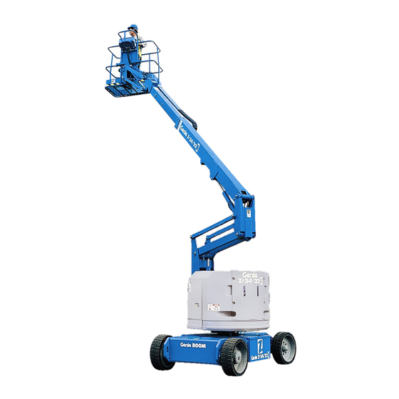
Terex Genie Z-34/22 IC Manuals
Manuals and User Guides for Terex Genie Z-34/22 IC. We have
7
Terex Genie Z-34/22 IC manuals available for free PDF download: Maintenance Manual, Service And Repair Manual, Operator's Manual
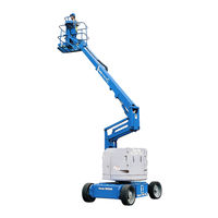
Terex Genie Z-34/22 IC Maintenance Manual (198 pages)
Brand:
Terex
| Category:
Boom Lifts
| Size: 8.19 MB
Table of Contents
Models Included in this Manual
3
Identifying the Correct Procedure for Your Model
5
Find Additional Manuals for Your Model
5
Revision History
6
Safety Rules
8
Table of Contents
10
Performance Specifications
17
Function Speeds - S-100, S-105 and S-100HD
17
Function Speeds - S-120, S-125 and S-120HD
18
Function Speeds - All Other Models
19
Drive Speeds
25
Torque Specifications
29
Tires and Wheels
29
Trax Torque Specifications
31
Engine Specifications
32
Engine Operator and Maintenance Manuals
32
Deutz Engine Models
33
Perkins Engine Models
34
Ford Engine Models
36
Kubota Engine Models
37
GM Engine Models
38
Continental Engine Models
38
Cummins Engine Models
39
Hydraulic Specifications
40
Hydraulic Relief Valves
40
Hydraulic and Drive Hub Fluid Capacities
43
Hydraulic Oil Specifications
45
Hydraulic Hose and Fitting Torque Specifications
48
Torque Procedure
49
Maintenance Procedures
51
Introduction
51
Maintenance Schedule
53
Pre-Delivery Preparation Report
54
Scheduled Maintenance Inspection Report - Quarterly or Frequent
55
Scheduled Maintenance Inspection Report - Annual
56
Programmed Maintenance Inspection Report - Booms
57
Commissioning Procedures
58
Perform 50 Hour Service
58
Perform Engine Maintenance - 50 Hours
58
Perform 150 Hour Service
59
Quarterly Maintenance Procedures
60
Check for Open Bulletins and Owner Registration
60
Battery Inspection
61
Inspect the Electrical Wiring
63
Inspect the Electrical Contactors - DC / Bi-Energy Models
64
Check the Exhaust System
65
Inspect the Tires, Wheels and Lug Nut Torque
66
Check the Generator Belts and Pulleys, Bi-Energy Models
66
Check the Oscillate Directional Valve Linkage (if Equipped)
68
Visual Inspection of the Hydraulic Oil
68
Inspect the Hydraulic Filters
69
Check and Adjust the Engine RPM
70
Test the Ground Control Override
76
Test the Alarm Package (if Equipped)
76
Test the Emergency Power System
77
Test the Engine Idle Select - Engine Models
78
Test the Fuel Select Operation - Gasoline/Lpg Models
79
Inspect the Calibration Decal - ALC1000 Models
81
Test the Recovery Mode System - ALC-1000 Models
82
Test the Platform Self-Leveling
83
Confirm the Proper Brake Configuration
84
Test the Drive Brakes
84
Test the Drive Speed - Stowed Position
85
Test the Drive Speed - Raised or Extended Position
85
Test the Drive Speed - Raised and Extended, ALC1000 Models
86
Test the Turntable Level Sensor
88
SX-105XC, SX-125XC, SX-135XC, SX-150 and SX-180
88
Test the Secondary Boom Angle Sensor - Z-135/70 and ZX-135/70
90
Test the Primary Boom Angle Sensor - Z-135/70 and ZX-135/70
92
Test the Primary Boom Angle Sensor
95
SX-105XC, SX-125XC, SX-135XC, SX-150 and SX-180
95
Test the Safety Envelope Limit Switches - Z-135/70, ZX-135/70
100
Test the Primary Boom Angle Sensor - Z-80/60
104
Test the Safety Envelope and Circuits - Z-80/60
105
Check the Safety Envelope Limit Switches and Angle Sensor - S-60X, S-80X, and S-60XC to S60XC-45000
107
Test the Safety Envelope and Circuits
109
And S-125
109
Test the Aircraft Protection System (if Equipped)
115
Test the Operator Protection Alarm (if Equipped)
117
Inspect the Boom Extend/Retract Cables - All Models
117
Test the Recovery Mode System - ALC600 Models
119
Test the Turntable Level Sensor - ALC600 Models
120
Test the Primary Boom Angle Sensor - ALC600 Models
122
Annual Maintenance Procedures
124
Grease the Turntable Rotation Bearing and Rotate Gear
124
Check the Turntable Rotation Bearing Bolts
125
Inspect for Turntable Bearing Wear
127
Check the Extendable Axle - S-100, S-105, S-120 and S-125
128
Perform Maintenance- Jib Rotate Bearing
129
Test the Bypass/Recovery Key Switch - ALC1000 Models
130
Grease the Platform Overload Mechanism (if Equipped)
133
Test the Platform Overload System - (if Equipped)
133
Test the Platform Overload System - ALC1000 Models
135
Test the Platform Load Sense System - S-60 HC
137
S-60/65, S-80/85 and S-80J Models
138
Inspect the Boom Extend/Retract Cables and Sheaves
139
Inspect the Boom Extend/Retract Cables and Sheaves
141
S-100, S-105, S-120, S-125, SX-105XC and SX-125XC
141
Inspect the Boom Extend and Retract Cables and Sheaves -
143
Check the Drive Hub Oil Level and Fastener Torque
146
Test the Dual Capacity and Platform Overload System - SX-105XC, SX-125XC and SX-135XC
150
Test the Dual Capacity and Platform Overload System - Z-45XC Models
152
Test the Dual Capacity and Platform Overload System - S-40XC, S-45XC, S-60HF, S-65HF, S-60XC from S60XCH-45001, S-65XC, S-80HF, S-85HF, S-80XC, S-85XC
154
Test the Platform Overload System - S-40HF, S-45HF, S-60J
156
S-80J, Z-45HF, Z-45 DC/FE from Z45EM-101
156
Perform Engine Maintenance
158
Programmed Maintenance Procedures
159
P0-1 Check the Track Tension and Fastener Torque, Trax Models
159
XC, S-65 XC, Z-62 Models
159
P0-2 Check the Track Tension and Fastener Torque, Trax Models - S-40, S-45, S-40 XC, S-45 XC Models
160
P0-3 Grease the Extendable Axles - S-100, S-105, S-120 and S-125
162
P0-4 Continental Engine Maintenance - under 1000 Hours
163
P0-5 Cummins Engine Maintenance - under 1000 Hours
164
P0-6 Deutz Engine Maintenance - under 1000 Hours
165
P0-7 Ford Engine Maintenance - under 1000 Hours
166
P0-8 Kubota Engine Maintenance - under 1000 Hours
167
P0-9 Perkins Engine Maintenance - under 1000 Hours
169
P0-10 GM .998L Engine Maintenance - under 1000 Hours
170
P0-11 GM 3.0L Engine Maintenance - under 1000 Hours
171
P1-1 Perform Engine Maintenance - 1000 Hours
172
P1-2 Replace the Drive Hub Oil
174
P1-3 Perform Engine Maintenance - 1500 Hours
177
P2-1 Perform Engine Maintenance - 2000 Hours
177
P2-2 Test or Replace the Hydraulic Oil
179
P2-3 Replace the Hydraulic Filters
180
P2-4 Check the Free-Wheel Configuration
182
P2-5 Check the Boom Wear Pads
184
P2-6 Check the Extendable Axle Wear Pads - S-100, S-105, S-120, S-125, S-100HD and S-120HD
187
P2-7 Check the Turntable Rotation Gear Backlash
187
P2-8 Grease the Steer Axle Wheel Bearings, All 2WD Models, Except S-60, S-65, Z-60 DC/FE and Z-62
188
P2-9 Grease the Steer Axle Wheel Bearings, 2WD Models
190
DC/FE and Z-62
190
Advertisement
Terex Genie Z-34/22 IC Service And Repair Manual (156 pages)
Brand:
Terex
| Category:
Lifting Systems
| Size: 8.26 MB
Table of Contents
Find a Manual for this Model
2
Revision History
3
Serial Number Legend
4
Safety Rules
5
Table of Contents
7
Specifications
14
Machine Specifications
14
Machine Component Weights
15
Performance Specifications
15
Hydraulic Specification
16
Hydraulic Component Specifications
18
Machine Torque Specifications
19
Kubota WG-972 Engine Specifications
20
GM .998L Engine Specifications
21
Kubota D1105 Engine Specifications
22
Perkins 403D-11 Engine Specifications
23
Perkins 403F-11 Engine Specifications
24
Hydraulic Hose and Fitting Torque Specifications
25
Torque Procedure
26
SAE and Metric Fasteners Torque Charts
28
Repair Procedures
29
Introduction
29
Platform Controls
31
Drive Joystick
31
How to Adjust the Drive Joystick
31
Boom Function Speed Controller Adjustments
33
Platform Components
35
Platform Leveling Slave Cylinder
35
How to Remove the Platform Leveling Slave Cylinder
35
How to Bleed the Leveling Slave Cylinder
35
Platform Rotator
36
How to Remove the Platform Rotator
36
How to Bleed the Platform Rotator
37
Platform Overload System
38
How to Calibrate the Platform Overload System (if Equipped)
38
Jib Boom Components
39
Jib Boom
39
How to Remove the Jib Boom
39
Jib Boom Bell Crank
40
How to Remove the Jib Boom Bell Crank
40
Jib Boom Lift Cylinder
40
How to Remove the Jib Boom Lift Cylinder
40
Primary Boom Components
42
Cable Track
42
How to Repair the Primary Boom Cable Track
42
Primary Boom
42
How to Shim the Primary Boom
42
How to Remove the Primary Boom
43
How to Disassemble the Primary Boom
45
Primary Boom Lift Cylinder
46
How to Remove the Primary Boom Lift Cylinder
46
Primary Boom Extension Cylinder
47
How to Remove the Primary Boom Extension Cylinder
47
Platform Leveling Master Cylinder
49
How to Remove the Platform Leveling Master Cylinder
49
Secondary Boom Components
51
Secondary Boom
52
How to Disassemble the Secondary Boom
52
Secondary Boom Lift Cylinders
55
How to Remove the Secondary Boom Lift Cylinders
55
Engines
57
Kubota Diesel Models
57
Timing Adjustment
57
How to Check the Glow Plugs
57
RPM Adjustment
57
How to Remove the Flex Plate
58
How to Install the Flex Plate
58
Coolant Temperature and Oil Pressure Switches
59
Kubota Gasoline / LPG Models
59
Choke Adjustment
59
Timing Adjustment
59
Carburetor Adjustment
59
RPM Adjustment
59
How to Remove the Flex Plate
60
How to Install the Flex Plate
60
Coolant Temperature and Oil Pressure Switches
61
Perkins Diesel Models
61
Timing Adjustment
61
RPM Adjustment
61
How to Remove the Flex Plate
62
How to Install the Flex Plate
62
Coolant Temperature and Oil Pressure Switches
63
GM .998L Models
63
Timing Adjustment
63
How to Remove the Flex Plate
64
How to Install the Flex Plate
64
Hydraulic Pumps
65
Auxiliary Pump
65
How to Test the Auxiliary Pump
65
How to Remove the Auxiliary Pump
65
Function Pump
66
How to Test the Function Pump
66
How to Removet the Function Pump
66
Drive Pump
67
How to Remove the Drive Pump
67
How to Prime the Drive Pump
67
Manifolds
68
8-1 Function Manifold Components
68
Valve Adjustments - Function Manifold
72
How to Adjust the Primary Boom down Relief Valve
72
How to Adjust the Secondary Boom down Relief Valve
72
Jib Boom and Platform / Jib Boom Rotate Manifold Components
73
Brake/Two-Speed Manifold Components
74
Traction Manifold Components, 2WD
75
Traction Manifold Components, 4WD
76
Valve Adjustments, 4WD Traction Manifold
78
Valve Coils
79
How to Test a Coil
79
Valve Coil Resistance Specification
79
How to Test a Coil Diode
80
Fuel and Hydraulic Tanks
81
Fuel Tank
81
How to Remove the Fuel Tank
81
Hydraulic Tank
82
How to Remove the Hydraulic Tank
82
Turntable Rotation Components
83
Turntable Rotation Hydraulic Motor
83
How to Remove the Turntable Rotation Motor
83
Axle Components
84
Hub and Bearings, 2WD Models
84
How to Remove the Hub and Bearings
84
How to Install the Hub and Bearings
84
Fault Codes
85
Introduction
85
How to Retrieve Engine Fault Codes Perkins 403F-11 Models
86
How to Retrieve Engine Fault Codes GM .998L Models
86
GM Fault Code Chart
88
Schematics
94
Introduction
94
Electrical Symbol Legend
95
Hydraulic Symbols Legend
96
Electrical Component and Wire Color Legends
97
Electrical Schematics - Gasoline/Lpg Models
100
Electrical Schematic - Gasoline/Lpg Kubota WG972 Models (from Serial Number Z3413-9461)
101
Ground Control Box Switch Panel Wiring Diagram - Gasoline/Lpg Models
105
Ground Control Box Terminal Strip Wiring Diagram - Gasoline/Lpg Models
106
Platform Control Box Wiring Diagram - Gasoline/Lpg Models
109
Electrical Schematic - Gasoline/Lpg Kubota WG972 Models (from Serial Number Z3413-9461)
111
Ground Control Box Switch Panel Wiring Diagram - Gasoline/Lpg GM .998L Models
115
Platform Control Box Wiring Diagram - Gasoline/Lpg Models
117
Electrical Schematics - Diesel Models
118
Electrical Schematic - Diesel Models from Z3413-9461 (ANSI / CSA)
119
Ground Control Box Switch Panel Wiring Diagram - Diesel Models
123
Ground Control Box Terminal Strip Wiring Diagram
124
Diesel Models from Serial Number Z3413-9461 (ANSI / CSA)
124
Platform Control Box Wiring Diagram
127
Diesel Models from Serial Number Z3413-9461 (ANSI / CSA)
127
Electrical Schematic - Diesel Models from Z3413-9461 (CE / AS)
129
Ground Control Box Switch Panel Wiring Diagram - Diesel Models
133
Ground Control Box Terminal Strip Wiring Diagram
134
Diesel Models from Serial Number Z3413-9461 (CE / AS)
134
Platform Control Box Wiring Diagram - Diesel Models from Serial Number
137
Z3413-9461 (Ansi / Csa)
137
Electrical Schematics - Options
138
GM .998L Engine Schematic
139
GM Engine Harness Diagram
140
Kubota D1105 Engine Schematic
143
Perkins 403F-11 Engine Schematic
144
Manifold and Limit Switch Wiring Diagram
147
Hydraulic Schematics
148
Hydraulic Schematic, 2WD Models
149
Hydraulic Schematic, 4WD Models
153
Terex Genie Z-34/22 IC Maintenance Manual (192 pages)
Brand:
Terex
| Category:
Boom Lifts
| Size: 5.99 MB
Table of Contents
Models Included in this Manual
3
Identifying the Correct Procedure for Your Model
5
Find Additional Manuals for Your Model
5
Revision History
6
Safety Rules
8
Table of Contents
10
Performance Specifications
17
Function Speeds - S-100, S-105 and S-100HD
17
Function Speeds - S-120, S-125 and S-120HD
18
Function Speeds - All Other Models
19
Drive Speeds
25
Torque Specifications
28
Tires and Wheels
28
Trax Torque Specifications
30
Engine Specifications
31
Engine Operator and Maintenance Manuals
31
Deutz Engine Models
32
Perkins Engine Models
33
Ford Engine Models
35
Kubota Engine Models
36
GM Engine Models
37
Continental Engine Models
37
Cummins Engine Models
38
Hydraulic Specifications
39
Hydraulic Relief Valves
39
Hydraulic and Drive Hub Fluid Capacities
42
Hydraulic Oil Specifications
44
Hydraulic Hose and Fitting Torque Specifications
47
Torque Procedure
48
Maintenance Procedures
50
Introduction
50
Maintenance Schedule
52
Pre-Delivery Preparation Report
53
Scheduled Maintenance Inspection Report - Quarterly or Frequent
54
Scheduled Maintenance Inspection Report - Annual
55
Programmed Maintenance Inspection Report - Booms
56
Commissioning Procedures
57
Perform 50 Hour Service
57
Perform Engine Maintenance - 50 Hours
57
Perform 150 Hour Service
58
Quarterly Maintenance Procedures
59
Check for Open Bulletins and Owner Registration
59
Battery Inspection
60
Inspect the Electrical Wiring
62
Inspect the Electrical Contactors - DC / Bi-Energy Models
63
Check the Exhaust System
64
Inspect the Tires, Wheels and Lug Nut Torque
65
Check the Generator Belts and Pulleys, Bi-Energy Models
65
Check the Oscillate Directional Valve Linkage (if Equipped)
67
Visual Inspection of the Hydraulic Oil
67
Inspect the Hydraulic Filters
68
Check and Adjust the Engine RPM
69
Test the Ground Control Override
75
Test the Alarm Package (if Equipped)
75
Test the Emergency Power System
76
Test the Engine Idle Select - Engine Models
77
Test the Fuel Select Operation - Gasoline/Lpg Models
78
Inspect the Calibration Decal - ALC1000 Models
79
Test the Recovery Mode System - ALC-1000 Models
80
Test the Platform Self-Leveling
82
Confirm the Proper Brake Configuration
82
Test the Drive Brakes
83
Test the Drive Speed - Stowed Position
83
Test the Drive Speed - Raised or Extended Position
84
Test the Drive Speed - Raised and Extended, ALC1000 Models
85
Test the Turntable Level Sensor
86
SX-105XC, SX-125XC, SX-135XC, SX-150 and SX-180
86
Test the Secondary Boom Angle Sensor - Z-135/70 and ZX-135/70
89
Test the Primary Boom Angle Sensor - Z-135/70 and ZX-135/70
91
Test the Primary Boom Angle Sensor
93
SX-105XC, SX-125XC, SX-135XC, SX-150 and SX-180
93
Test the Safety Envelope Limit Switches - Z-135/70, ZX-135/70
98
Test the Primary Boom Angle Sensor - Z-80/60
102
Test the Safety Envelope and Circuits - Z-80/60
103
Check the Safety Envelope Limit Switches and Angle Sensor - S-60X, S-80X, and S-60XC to S60XC-45000
105
Test the Safety Envelope and Circuits
107
And S-125
107
Test the Aircraft Protection System (if Equipped)
113
Test the Operator Protection Alarm (if Equipped)
115
Inspect the Boom Extend/Retract Cables - All Models
115
Test the Recovery Mode System - ALC-600 Models
116
Test the Turntable Level Sensor - S-40HF, S-45HF, S-40XC, S-45XC, S- 60HF, S-65HF, S-60J, S-60XC from S60XCH-45001, S-65XC
117
S-80Hf, S-85Hf, S-80Xc, S-85Xc
117
Test the Primary Boom Angle Sensor - S-40HF, S-45HF, S-40XC
119
S-45XC, S-60HF, S-65HF, S-60J, S-60XC from S60XCH-45001
119
S-65Xc, S-80Hf, S-85Hf, S-80Xc, S-85Xc
119
Annual Maintenance Procedures
121
Grease the Turntable Rotation Bearing and Rotate Gear
121
Check the Turntable Rotation Bearing Bolts
122
Inspect for Turntable Bearing Wear
124
Check the Extendable Axle - S-100, S-105, S-120 and S-125
125
Perform Maintenance- Jib Rotate Bearing
126
Test the Bypass/Recovery Key Switch - ALC1000 Models
127
Grease the Platform Overload Mechanism (if Equipped)
129
Test the Platform Overload System - All Models
130
S-80HF, S-85HF, S-80XC, S-85XC and Z-45XC Models)
130
Test the Platform Overload System - ALC1000 Models
132
Test the Platform Load Sense System - S-60 HC
133
Inspect the Boom Extend/Retract Cables and Sheaves
134
S-60/65 and S-80/85 Models
134
Inspect the Boom Extend/Retract Cables and Sheaves - S-100, S-105, S-120, S-125, SX-105XC and SX-125XC
136
Inspect the Boom Extend and Retract Cables and Sheaves -
138
Check the Drive Hub Oil Level and Fastener Torque
142
Test the Dual Capacity and Platform Overload System - SX-105XC, SX-125XC and SX-135XC
146
Test the Dual Capacity and Platform Overload System - Z-45XC Models
148
Test the Dual Capacity and Platform Overload System
148
S-65Xc, S-80Hf, S-85Hf, S-80Xc, S-85Xc
149
Test the Platform Overload System - S-40HF, S-45HF, Z-45HF, Z-45 DC/FE from Z45EM-101
151
Perform Engine Maintenance
152
Advertisement
Terex Genie Z-34/22 IC Service And Repair Manual (133 pages)
Brand:
Terex
| Category:
Boom Lifts
| Size: 4.46 MB
Table of Contents
Introduction
2
Find a Manual for this Model
2
Revision History
3
Serial Number Legend
4
Safety Rules
5
Table of Contents
7
Specifications
13
Machine Specifications
13
Machine Component Weights
14
Performance Specifications
14
Hydraulic Oil Specifications
15
Hydraulic Component Specifications
18
Machine Torque Specifications
19
Kubota WG-972 Engine Specifications
20
GM .998L Engine Specifications
21
Kubota D1105 Engine Specifications
22
Perkins 403D-11 Engine Specifications
23
Perkins 403F-11 Engine Specifications
24
Hydraulic Hose and Fitting Torque Specifications
25
Torque Procedure
26
Repair Procedures
28
Introduction
28
Platform Controls
30
Drive Joystick
30
How to Adjust the Drive Joystick
30
Boom Function Speed Controller Adjustments
32
Platform Components
34
Platform Leveling Slave Cylinder
34
How to Remove the Platform Leveling Slave Cylinder
34
How to Bleed the Leveling Slave Cylinder
34
Platform Rotator
35
How to Remove the Platform Rotator
35
How to Bleed the Platform Rotator
36
Platform Overload System
37
How to Calibrate the Platform Overload System (if Equipped)
37
Jib Boom Components
38
Jib Boom
38
How to Remove the Jib Boom
38
Jib Boom Bell Crank
39
How to Remove the Jib Boom Bell Crank
39
Jib Boom Lift Cylinder
39
How to Remove the Jib Boom Lift Cylinder
39
Primary Boom Components
41
Cable Track
41
How to Repair the Primary Boom Cable Track
41
Primary Boom
41
How to Shim the Primary Boom
41
How to Remove the Primary Boom
42
How to Disassemble the Primary Boom
44
Primary Boom Lift Cylinder
45
How to Remove the Primary Boom Lift Cylinder
45
Primary Boom Extension Cylinder
46
How to Remove the Primary Boom Extension Cylinder
46
Platform Leveling Master Cylinder
48
How to Remove the Platform Leveling Master Cylinder
48
Secondary Boom Components
49
Secondary Boom
50
How to Disassemble the Secondary Boom
50
Secondary Boom Lift Cylinders
53
How to Remove the Secondary Boom Lift Cylinders
53
Engines
55
Kubota Diesel Models
55
Timing Adjustment
55
How to Check the Glow Plugs
55
RPM Adjustment
55
How to Remove the Flex Plate
56
How to Install the Flex Plate
56
Coolant Temperature and Oil Pressure Switches
57
Kubota Gasoline / LPG Models
57
Choke Adjustment
57
Timing Adjustment
57
Carburetor Adjustment
57
RPM Adjustment
57
How to Remove the Flex Plate
58
How to Install the Flex Plate
58
Coolant Temperature and Oil Pressure Switches
59
Perkins Diesel Models
59
Timing Adjustment
59
RPM Adjustment
59
How to Remove the Flex Plate
60
How to Install the Flex Plate
60
Coolant Temperature and Oil Pressure Switches
61
GM .998L Models
61
Timing Adjustment
61
How to Remove the Flex Plate
62
How to Install the Flex Plate
62
Hydraulic Pumps
63
Auxiliary Pump
63
How to Test the Auxiliary Pump
63
How to Remove the Auxiliary Pump
63
Function Pump
64
How to Removet the Function Pump
64
Drive Pump
65
How to Remove the Drive Pump
65
How to Prime the Drive Pump
65
Manifolds
66
8-1 Function Manifold Components
66
Valve Adjustments - Function Manifold
70
How to Adjust the System Relief Valve
70
How to Adjust the Primary Boom down Relief Valve
70
How to Adjust the Secondary Boom down Relief Valve
71
Jib Boom and Platform / Jib Boom Rotate Manifold Components
73
Brake/Two-Speed Manifold Components
74
Traction Manifold Components, 2WD
75
Traction Manifold Components, 4WD
76
Valve Adjustments, 4WD Traction Manifold
78
Valve Coils
79
How to Test a Coil
79
Valve Coil Resistance Specification
79
How to Test a Coil Diode
80
Fuel and Hydraulic Tanks
81
Fuel Tank
81
How to Remove the Fuel Tank
81
Hydraulic Tank
82
How to Remove the Hydraulic Tank
82
Turntable Rotation Components
83
Turntable Rotation Hydraulic Motor
83
How to Remove the Turntable Rotation Motor
83
Axle Components
84
Hub and Bearings, 2WD Models
84
How to Remove the Hub and Bearings
84
How to Install the Hub and Bearings
84
Fault Codes
85
Introduction
85
How to Retrieve Engine Fault Codes Perkins 403F-11 Models
86
How to Retrieve Engine Fault - Codes GM .998L Models
87
Schematics
93
Introduction
93
Electrical Symbol Legend
94
Hydraulic Symbols Legend
95
Electrical Component and Wire Color Legends
96
Electrical Schematics - Gasoline/Lpg Models
99
Electrical Schematic - Gasoline/Lpg Models
100
Electrical Schematic, Functions - Gasoline/Lpg Models
101
Electrical Schematic, PSI DF Engine - Gasoline/Lpg Models
104
Electrical Schematics - Diesel Models
105
Electrical Schematic - Diesel Models (ANSI / CSA)
106
Electrical Schematic, Functions - Diesel Models ANSI / CSA
107
Electrical Schematic - Diesel Models (CE / AS)
110
Electrical Schematics - Options
113
Kubota D1105 Engine Schematic, Options
114
Perkins 403F-11 Engine Schematic, Options
115
Manifold and Limit Switch Wiring Diagram - Diesel Models, Options
118
Manifold and Limit Switch Wiring Diagram - Gasoline/Lpg Models, Options
119
Lift Guard Contact Alarm Wiring Diagram, Options
122
Fuel Level Telematics Wiring Diagram, Options
123
Hydraulic Schematics
125
Hydraulic Schematic, 2WD Models
126
Hydraulic Schematic, 4WD Models
130
Terex Genie Z-34/22 IC Maintenance Manual (185 pages)
Brand:
Terex
| Category:
Boom Lifts
| Size: 4.09 MB
Table of Contents
Models Included in this Manual
3
Identifying the Correct Procedure for Your Model
5
Find Additional Manuals for Your Model
5
Revision History
6
Safety Rules
8
Table of Contents
10
Performance Specifications
17
Function Speeds - S-100, S-105 and S-100HD
17
Function Speeds - S-120, S-125 and S-120HD
18
Function Speeds - All Other Models
19
Drive Speeds
25
Torque Specifications
29
Tires and Wheels
29
Trax Torque Specifications
31
Engine Specifications
32
Engine Operator and Maintenance Manuals
32
Deutz Engine Models
33
Perkins Engine Models
34
Ford Engine Models
36
Kubota Engine Models
37
GM Engine Models
38
Continental Engine Models
38
Cummins Engine Models
39
Hydraulic Specifications
40
Hydraulic Relief Valves
40
Hydraulic and Drive Hub Fluid Capacities
43
Hydraulic Oil Specifications
45
Hydraulic Hose and Fitting Torque Specifications
48
Torque Procedure
49
Maintenance Procedures
51
Introduction
51
Maintenance Schedule
53
Pre-Delivery Preparation Report
54
Scheduled Maintenance Inspection Report - Quarterly or Frequent
55
Scheduled Maintenance Inspection Report - Annual
56
Programmed Maintenance Inspection Report - Booms
57
Commissioning Procedures
58
Perform 50 Hour Service
58
Perform Engine Maintenance - 50 Hours
58
Perform 150 Hour Service
59
Quarterly Maintenance Procedures
60
Check for Open Bulletins and Owner Registration
60
Battery Inspection
61
Inspect the Electrical Wiring
63
Inspect the Electrical Contactors - DC / Bi-Energy Models
64
Check the Exhaust System
65
Inspect the Tires, Wheels and Lug Nut Torque
66
Check the Generator Belts and Pulleys, Bi-Energy Models
66
Check the Oscillate Directional Valve Linkage (if Equipped)
68
Visual Inspection of the Hydraulic Oil
68
Inspect the Hydraulic Filters
69
Check and Adjust the Engine RPM
70
Test the Ground Control Override
76
Test the Alarm Package (if Equipped)
76
Test the Emergency Power System
77
Test the Engine Idle Select - Engine Models
78
Test the Fuel Select Operation - Gasoline/Lpg Models
79
Inspect the Calibration Decal - ALC1000 Models
81
Test the Recovery Mode System - ALC-1000 Models
82
Test the Platform Self-Leveling
83
Confirm the Proper Brake Configuration
84
Test the Drive Brakes
84
Test the Drive Speed - Stowed Position
85
Test the Drive Speed - Raised or Extended Position
85
Test the Drive Speed - Raised and Extended, ALC1000 Models
86
Test the Turntable Level Sensor
88
SX-105XC, SX-125XC, SX-135XC, SX-150 and SX-180
88
Test the Secondary Boom Angle Sensor - Z-135/70 and ZX-135/70
90
Test the Primary Boom Angle Sensor - Z-135/70 and ZX-135/70
92
Test the Primary Boom Angle Sensor
95
SX-105XC, SX-125XC, SX-135XC, SX-150 and SX-180
95
Test the Safety Envelope Limit Switches - Z-135/70, ZX-135/70
100
Test the Primary Boom Angle Sensor - Z-80/60
104
Test the Safety Envelope and Circuits - Z-80/60
105
Check the Safety Envelope Limit Switches and Angle Sensor - S-60X, S-80X, and S-60XC to S60XC-45000
107
Test the Safety Envelope and Circuits
109
And S-125
109
Test the Aircraft Protection System (if Equipped)
115
Test the Operator Protection Alarm (if Equipped)
117
Inspect the Boom Extend/Retract Cables - All Models
117
Test the Recovery Mode System - ALC600 Models
118
Test the Turntable Level Sensor - ALC600 Models
119
Test the Primary Boom Angle Sensor - ALC600 Models
122
Terex Genie Z-34/22 IC Service And Repair Manual (119 pages)
Brand:
Terex
| Category:
Boom Lifts
| Size: 4.67 MB
Table of Contents
Introduction
2
Find a Manual for this Model
2
Revision History
3
Serial Number Legend
4
Safety Rules
5
Table of Contents
7
Specifications
13
Machine Specifications
13
Performance Specifications
14
Hydraulic Specification
14
Hydraulic Component Specifications
16
Machine Torque Specifications
18
Kubota D-905 Engine Specifications
19
Kubota DF-752 Engine Specifications
20
Perkins 403C-11 Engine Specifications
21
Hydraulic Hose and Fitting Torque Specifications
22
Torque Procedure
23
SAE and Metric Fasteners Torque Charts
24
September
24
Repair Procedures
25
Introduction
25
Section 3 Repair Procedures
25
About this Section
26
Platform Controls
27
Drive Joystick
27
How to Adjust the Drive Joystick
27
Boom Function Speed Controller Adjustments
29
Platform Components
31
Platform Leveling Slave Cylinder
31
How to Remove the Platform Leveling Slave Cylinder
31
How to Bleed the Leveling Slave Cylinder
31
Platform Rotator
32
How to Remove the Platform Rotator
32
How to Bleed the Platform Rotator
33
Platform Overload System
34
How to Calibrate the Platform Overload System (if Equipped)
34
Jib Boom Components
36
Jib Boom
36
How to Remove the Jib Boom
36
Jib Boom Bell Crank
37
How to Remove the Jib Boom Bell Crank
37
Jib Boom Lift Cylinder
37
How to Remove the Jib Boom Lift Cylinder
37
Primary Boom Components
39
Cable Track
39
How to Repair the Primary Boom Cable Track
39
Primary Boom
39
How to Shim the Primary Boom
39
How to Remove the Primary Boom
40
How to Disassemble the Primary Boom
42
Primary Boom Lift Cylinder
43
How to Remove the Primary Boom Lift Cylinder
43
Primary Boom Extension Cylinder
44
How to Remove the Primary Boom Extension Cylinder
44
Platform Leveling Master Cylinder
46
How to Remove the Platform Leveling Master Cylinder
46
Secondary Boom Components
48
Secondary Boom
49
How to Disassemble the Secondary Boom
49
Secondary Boom Lift Cylinders
52
How to Remove the Secondary Boom Lift Cylinders
52
Engines
54
Kubota Diesel Models
54
Timing Adjustment
54
How to Check the Glow Plugs
54
RPM Adjustment
54
How to Remove the Flex Plate
55
How to Install the Flex Plate
55
Coolant Temperature and Oil Pressure Switches
56
Kubota Gasoline / LPG Models
56
Choke Adjustment
56
Timing Adjustment
56
Carburetor Adjustment
56
RPM Adjustment
56
September
56
How to Remove the Flex Plate
57
How to Install the Flex Plate
57
Coolant Temperature and Oil Pressure Switches
58
Perkins Diesel Models
58
Timing Adjustment
58
RPM Adjustment
58
How to Remove the Flex Plate
59
How to Install the Flex Plate
59
Coolant Temperature and Oil Pressure Switches
60
Hydraulic Pumps
61
Auxiliary Pump
61
How to Test the Auxiliary Pump
61
How to Remove the Auxiliary Pump
61
Function Pump
62
How to Test the Function Pump
62
How to Removet the Function Pump
62
Drive Pump
63
How to Remove the Drive Pump
63
How to Prime the Drive Pump
63
Manifolds
64
8-1 Function Manifold Components
64
Valve Adjustments - Function Manifold
68
How to Adjust the Primary Boom down Relief Valve
68
How to Adjust the Secondary Boom down Relief Valve
68
Jib Boom and Platform / Jib Boom Rotate Manifold Components
69
Brake/Two-Speed Manifold Components
70
Traction Manifold Components, 2WD
71
Traction Manifold Components, 4WD
72
Valve Adjustments, 4WD Traction Manifold
74
Valve Coils
75
How to Test a Coil
75
Valve Coil Resistance Specification
75
How to Test a Coil Diode
76
Fuel and Hydraulic Tanks
77
Fuel Tank
77
How to Remove the Fuel Tank
77
Hydraulic Tank
78
How to Remove the Hydraulic Tank
78
Turntable Rotation Components
79
Turntable Rotation Hydraulic Motor
79
How to Remove the Turntable Rotation Motor
79
Axle Components
80
Hub and Bearings, 2WD Models
80
How to Remove the Hub and Bearings
80
How to Install the Hub and Bearings
80
Schematics
81
Introduction
81
September
81
Electrical Symbol Legend
82
Hydraulic Symbols Legend
83
Electrical Component and Wire Color Legends
84
Electrical Schematics - Gasoline/Lpg Models
87
Electrical Schematic - Gasoline/Lpg Models
88
Ground Control Box Switch Panel Wiring Diagram - Gasoline/Lpg Models
92
Ground Control Box Terminal Strip Wiring Diagram - Gasoline/Lpg Models
93
Platform Control Box Wiring Diagram - Gasoline/Lpg Models
96
Electrical Schematics - Diesel Models
97
Electrical Schematic - Diesel Models
98
Ground Control Box Switch Panel Wiring Diagram - Diesel Models
102
Ground Control Box Terminal Strip Wiring Diagram - Diesel Models
103
Platform Control Box Wiring Diagram - Diesel Models
106
Electrical Schematics - Options
107
Platform Control Box Wiring Diagram - Options
108
Manifold and Limit Switch Wiring Diagram
109
Hydraulic Schematics
111
Hydraulic Schematic, 2WD Models
112
Hydraulic Schematic, 4WD Models
116
Terex Genie Z-34/22 IC Operator's Manual (57 pages)
Brand:
Terex
| Category:
Lifting Systems
| Size: 5.61 MB
Table of Contents
Table of Contents
2
Introduction
3
Symbol and Hazard Pictorials Definitions
8
General Safety
10
Personal Safety
13
Work Area Safety
14
Legend
22
Controls
23
Inspections
25
Operating Instructions
38
Transport and Lifting Instructions
46
Maintenance
50
Specifications
53
Contents of EC Declaration of Conformity
56
Advertisement
Related Products
Terex Genie Z-34/22 DC
Terex Genie Z-34/22 N
Terex Genie Z-34/22 BE
Terex Genie Z-34/22N
Terex Genie Z-34/22DC
Terex Genie Z-34/22
Terex Z34F-14000
Terex Genie Z-34N
Terex Genie Z-34 IC
Terex Z34NF-17000
Terex Categories
Boom Lifts
Lifting Systems
Construction Equipment
Scissor Lifts
Compact Loader
More Terex Manuals
Login
Sign In
OR
Sign in with Facebook
Sign in with Google
Upload manual
Upload from disk
Upload from URL