
Subscribe to Our Youtube Channel
Related Manuals for Paragon GZ584E


Summary of Contents for Paragon GZ584E
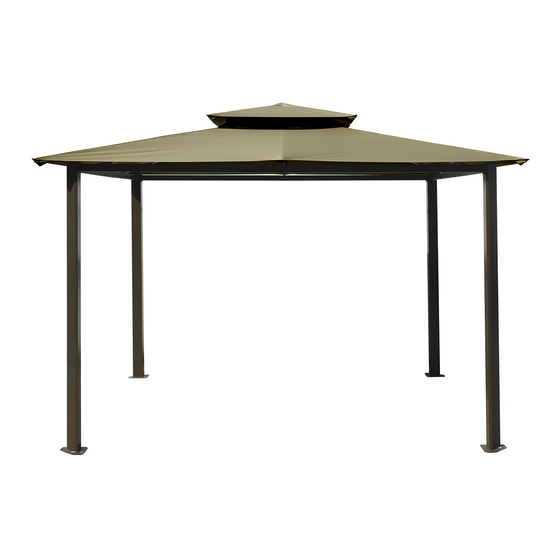
- Page 1 Gazebo GZ584E Assembly Instructions 7’1” max. 9’2” Paragon Group USA Customer Service:(877) 782 4482 Email:cs-outdoors@paragongroupusa.com...
-
Page 2: Introduction
Introduction Thank you for purchasing the Gazebo GZ584E. When properly assembled and maintained, this gazebo will provide many years of enjoyment! These instructions include helpful hints and important information needed to safely assemble and properly maintain the gazebo. Please read these instructions completely before you begin. -
Page 3: Table Of Contents
Safety Advice Table of Contents • The gazebo must be positioned and fixed Introduction..........on a flat level surface. Table of Contents........• Dispose of all plastic bags safely. Keep List of Parts..........them out of the reach of children. Step 1 Assembling the Corner Profiles.. -
Page 4: List Of Parts
List of Parts The gazebo is shipped in three cartons. These cartons are heavy. Be careful when lifting them. Wear proper safety gear including work shoes, gloves and goggles. The parts are identified by removable stickers. Place all the parts for each step in staging areas, checking that you have all parts as you go. If any parts are missing or damaged, contact customer service before beginning assembly: Customer Service:(877) 782 4482 Email:cs-outdoors@paragongroupusa.com Profile... - Page 5 Profile Qty Step Profile Qty Step Fabric canopy top Fabric canopy Screw Screw 1/4’’x55mm 1/4’’x15mm We included some extra screws and bolts for your convenience. Screw 5/16’’x15mm Screw 1/4’’x38mm of 18...
-
Page 6: Step 1 Assembling The Corner Profiles
STEP 1 Assembling the Corner Profiles Place all the parts on a level surface . Make sure the pieces are in the correct positions before assembling. Carefully follow the order of assembly to ensure an easy installation. Wear proper safety gear including work shoes, gloves and goggles. Components Place corner profiles (1) parallel to each other on the ground. -
Page 7: Step 2 Assembling The Roof Profiles
STEP 2 Assembling the Roof Profiles Place all the parts on a level surface. Make sure the pieces are in the correct positions before assembling. Carefully follow the order of assembly to ensure an easy installation. Wear proper safety gear including work shoes, gloves and goggles. Components Insert end of long roof profile (2) into long roof profile (3) as shown. -
Page 8: Step 3 Attaching The Roof Profiles To Corner Profiles
STEP 3 Attaching Roof Profiles to Corner Profiles Attach long roof profile sets (2,3) to corner profiles (1) as shown. Fasten with bolts (22). Repeat to make two sets. Components Screw (22) x 32 Attach short roof profile sets (4,5) to corner profiles (1) as shown. -
Page 9: Step 4 Attaching The Roof Connectors
STEP 4 Attaching the Roof Connectors to Roof and Corner Profiles Components Attach roof connectors (16) to corner profile covers (15) with bolts(21) fasten as shown. Screw(21) Attach roof connectors(16) and (28) to roof profiles(2) and (4) with bolts(29) fasten as Screw(29) shown. -
Page 10: Step 5 Attaching The Corner Roof Gables
STEP 5 Attaching the Corner Roof Gables IMPORTANT: The roof gable profiles (6) have small protrusions (spring buttons) on their underside. The end with the protrusions is connected to the top gable connector (13). The roof gable extension (11) has a small protrusion underneath which will snap into one of the holes in roof gable extension (9) while stretching the canopy. - Page 11 Connect one roof gable profiles assembly (6,12) and one roof gable profiles assembly (6,11) opposite each other to top gable connector (13) until the small protrusion on their undersides snap into the holes on the underside of top gable connector (13). ATTENTION: The tunnels of top gable connector (13) are marked, in order to avoid mistakes when inserting the roof...
- Page 12 Using at least two people, slide the other two roof gable assemblies (6,12 - 6,11) into tunnels of top gable connector (13) until the small protrusion on their undersides snap into the holes on the underside of top gable connector (13). ATTENTION: The tunnels of top gable connector (13) are marked, in order to avoid...
- Page 13 Connect the two roof gable profiles (6,12) and (6,11,9) to roof connectors (16) on opposite corner profiles (1). Fasten with screws (23) as shown. 11/12 Slide roof gable extension (9) over roof gable extension (11) until the small protrusion on it’s underside snaps into the third hole on the underside of roof gable extension (9).
-
Page 14: Step 6 Attaching The Center Roof Gables
STEP 6 Attaching the Center Roof Gables IMPORTANT: The roof gable profiles (7,8) have small protrusions (spring buttons) underneath. The end with the protrusions is connected to the top gable connector (13). Insert ends with push buttons of roof gable profiles Components (7) on short side of the gazebo into marked tunnels of Roof gable... -
Page 15: Step 8 Placing The Canopy
STEP 8 Placing the Canopy WARNING!! : When inserting the roof profiles into the fabric pockets of the canopy, you MUST use both hands holding the large piece of roof fabric in order to stretch it. Don’t try to stretch it and pull it just by pulling the pockets! It will tear the pockets as Sunbrella fabric is not elastic by nature. - Page 16 Using at least two people, place the large canopy (19) carefully over the small canopy (18) and three roof gable profiles (6+12) as shown. Stretch the canopy and slide profiles into fabric pockets in large canopy rim (19). Use TWO hands to pull the fabric backward until the roof profiles slide firmly into the pockets.
-
Page 17: Optional Securing The Gazebo To A Concrete Floor Or Wood Deck
Optional Securing the Gazebo to a Concrete Floor or Wood Deck Concrete Floor: Components 1. Using an electric concrete drill, drill holes into the concrete floor, corresponding to the holes in the support plates. 2. Insert concrete bolts (25) into the holes and hammer into place, using a mallet. Concrete bolts, washers and nuts (25) x 12 3. - Page 18 Gazebo GZ584E Assembly Instructions WARRANTY: Warranty covers damage due to manufacturing defects only. Warranty does not cover weather inflicted damage (Force Majeure) and/or damages caused by not following assembly instructions and adhering to warnings in manual. WARNING : In order to prevent possible damage to fabric and/ or structure, fabric roof should be removed before wind storms, or major inclement weather events.
Need help?
Do you have a question about the GZ584E and is the answer not in the manual?
Questions and answers