Table of Contents
Advertisement
Quick Links
- Data Brochure
Zone Control 367
Occupied
Power
UnOccupied
Heat Required
Optimum Start / Stop
24 hr. Timer
Timer Active
System Pump
70°F
(21°C)
12 hrs.
Zone 1 / Lo stage /
1
• Dial the desired duration
Open / Cooling
6
18
of the UnOccupied period.
Zone 2 / Hi stage /
• Press start button at the time of day
2
Close / Ventilation
you want the UnOcc. period to begin.
Timer Active light turns on.
Zone 3 / Lo stage
3
Open
0
24
40
100
UnOccupied
(4)
(38)
Zone 4 / Hi stage
4
Close
Duration
UnOccupied
Zone 5 / Lo stage
Start
5
Open
Zone 6 / Hi stage
6
0 = always Occupied
Close
24 = always UnOccupied
Zone Control 367
One & Two Stage / One Stage & Floating
Output
System
Pump
Input
120 V (ac)
Power
Supply
70
70
70
70
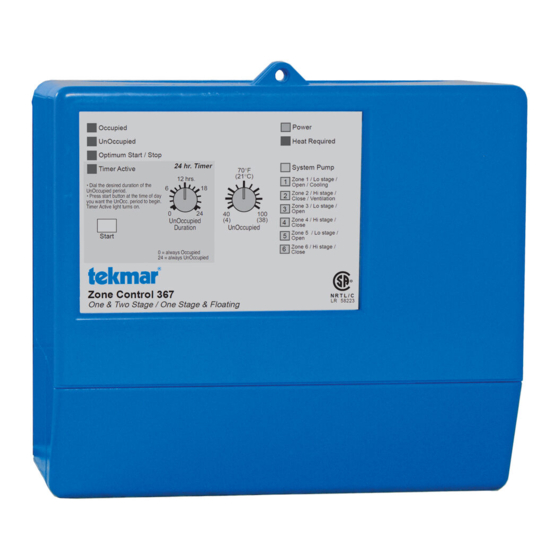
The Zone Control 367 is a microprocessor-based energy management control that uses PID
logic to control the temperature in up to 6 heating zones. Multiple zone controls can be daisy
chained together for up to 36 zones of heating. The 367 allows a variety of zoning options
including: single stage zones, two stage zones and modulating zones. The 367 is designed
to stagger zone operating times in order to minimize boiler short cycling and allow boiler
purging between cycles. The 367 has a built in night setback timer and a separate Optimum
Start / Stop feature for each zone. When the 367 is used with a tekmar reset control, the 367
provides indoor temperature feedback that adjusts the supply water temperature in order to
satisfy the zone with the highest heat load. Central ventilation, mechanical cooling and free
cooling systems can also be directly controlled through the 367.
Control Strategy . . . . . . . . . . . . . . . . pg. 2
Basic Sequence of Operation . . . . .
Basic Installation . . . . . . . . . . . . . . . pg. 6
Basic Settings . . . . . . . . . . . . . . . . . . pg. 9
Advanced Sequence of Operation . . pg. 10 Limited Warranty . . . . . pg. 16
Advanced Installation . . . . . . . . . . . . pg. 12
Occupied
UnOccupied
Optimum Start / Stop
24 hr. Timer
Timer Active
12 hrs.
• Dial the desired duration of the
6
18
UnOccupied period.
• Press start button at the time of day
you want the UnOcc. period to begin.
Timer Active light turns on.
0
24
UnOccupied
Duration
Start
0 = always Occupied
24 = always UnOccupied
Zone Control 367
One & Two Stage / One Stage & Floating
Do not apply power here
1
2
3
4
5
6
7
8 9
System
Power
Com
RTU
RTU
Com
RTU
Pmp
Pmp
N
L
Sen
1
2
Sen
3
T I M E
PRGM
1
2
AMPM
UNOCC
OVR
S
M
T
W T F
S
70
70
Input
Input
tekmar RTUs or
tekmar
Timer
Indoor Sensors
Power
Heat Required
System Pump
70°F
(21°C)
Zone 1 / Lo stage /
1
Open / Cooling
Zone 2 / Hi stage /
2
Close / Ventilation
Zone 3 / Lo stage /
3
Open
40
100
(4)
(38)
Zone 4 / Hi stage /
4
Close
UnOccupied
Zone 5 / Lo stage /
5
Open
Zone 6 / Hi stage /
6
Close
R
N R T L / C
LR 58223
Caution: Signal wiring must be rated at least 300V
10
11 12 13 14
15 16 17
18
RTU
Com
RTU
RTU
UnO
Zo
Com
Zo
Out
4
Sen
5
6
Sw
Out
Sen
In
Sen
LR 58233 E150539
LR 58233 E150539
Output
Input
tekmar Reset
tekmar Zone
Outdoor
Control
Control
Sensor
Advanced Settings . . . pg. 13
pg. 3
Testing the Control . . . pg. 13
Error Messages . . . . . . pg. 15
Technical Data . . . . . . . pg. 16
Thermal Motor
Optimum Start
One Stage & Floating
Occ/UnOcc
Zone 1 Cooling
Zone 2 Ventilating
Zone 2 Heating
Zone
1,2
3
4
5 6
Zone 1 Heating
Occ. only
Off
One & Two Stage
65°F
0°F
130 sec.
100
30
85
40
Off
-40
Off
30
230
Max. Room
Design Outdoor
Floating Motor
Speed
T est
Made in Canada by
Aug 95
tekmar Control Systems Ltd.
31000266
Power
120 V 50/60 Hz 8 VA
Pump Relay
120 V (ac) 10 A 1/3 hp, pilot duty 240 VA
Zone Relays
120 V (ac) 6 A 1/3 hp, pilot duty 240 VA
19
20
21 22
23
24 25
26 27
Com
Com
Com
1-2
1
2
3-4
3
4
5-6
5
6
M
Input
Output
Zone Valve or
or
Cooling
Zone Pump
D 367
07/95
200
Outputs
Zone Valves or
Zone Pumps
M
M
M
M
M
or
Ventilation
Advertisement
Table of Contents

Related Manuals for Tekmar Zone Control 367


Summary of Contents for Tekmar Zone Control 367
- Page 1 0 = always Occupied Close 24 = always UnOccupied Start / Stop feature for each zone. When the 367 is used with a tekmar reset control, the 367 Zone Control 367 One & Two Stage / One Stage & Floating provides indoor temperature feedback that adjusts the supply water temperature in order to satisfy the zone with the highest heat load.
- Page 2 Control Strategy ZONING OPERATION In a multiple zone heating system, the zones may have different internal heat gains, heat losses or different temperature settings. Each zone must therefore have individual temperature control. For maximum comfort, the heat should be continuously supplied to the zone at the same rate the zone is losing heat.
-
Page 3: Basic Sequence Of Operation
Design Outdoor POWERING UP THE CONTROL After the Zone Control 367 is powered up, a software version code is displayed for 2 seconds and then the red indicator lights are then turned on for 4 seconds. When the control is T est powered up, the green Power light remains on continuously. - Page 4 Zone Control Operation with a tekmar Outdoor Reset Control Zone Control Boiler or Heating System Control The 367 can provide indoor temperature feedback to a tekmar Reset Control. When multiple Zone Controls are used, each Zone Control sequentially passes the information to the tekmar Reset Control in...
-
Page 5: Cooling Operation
SCHD AMPM UNOCC is closed, the 367 registers an UnOccupied signal. A tekmar Timer 031 is available which WeTh Fr can be programmed to provide individual UnOccupied schedules for each day of the week with up to two separate UnOccupied events per day. For more information on the Timer... - Page 6 STEP ONE GETTING READY Check the contents of this package. If any of the contents listed are missing or damaged, please contact your wholesaler or tekmar sales representative for assistance. Type 367 includes: •...
-
Page 7: Electrical Connections To The Control
367 and continue this process for each additional 367. The Zo Out terminal on the last 367 in the chain can be connected to the Zo In terminal on a tekmar reset control. Note The wires from the Zone Control are polarity sensitive. The system will not operate if the wires are reversed. -
Page 8: Output Connections
Sen — RTU 4 (8 and 10) terminals. Common block for RTU 1 and RTU 2 DIP switch set to Zone 1 Heating • If the common block is used for a single One Stage heating zone, connect the RTU or Indoor Sensor to terminals Com Sen —... - Page 9 Test the Sensors Ω In order to test the sensors and Room Temperature Units (RTUs), the actual temperature at each sensor and RTU location must be measured. A good quality digital thermometer Ω with a surface temperature probe is recommended for ease of use and accuracy of testing.
-
Page 10: Dip Switch Settings
Floating Motor Speed 130 sec. This dial has no effect on the operation of the control unless modulating zone valves are used. See the Advanced section of this brochure for more information. Using the Internal 24 hr. Timer Floating Motor Speed First determine the length of time required for the UnOccupied period and turn the... -
Page 11: Free Cooling
This function should only be used if the 367 is not connected to a tekmar reset control. When the Design Outdoor dial is turned up from the Off position and an outdoor sensor is present, the demand limiting function is enabled. Based on the outdoor temperature, the control restricts the maximum on time of the zone relays. -
Page 12: Advanced Installation
Advanced Installation This section supplements the basic installation that begins on page 6. Sensor and Unpowered Input Connections Do not apply power to these terminals as this will damage the control. 20 21 Floating Action RTU and Indoor Sensor Connections It is best to start the Floating Action heating zones at output relays 1 and 2 and work towards output relays 5 and 6 . -
Page 13: Test Sequence
OPERATIONAL TEST OF CONTROL FUNCTIONS The Zone Control 367 has a test routine which is used to test the main control functions. The 367 continually checks the sensors and displays an error message whenever a fault is found. See page 15 for the list of error messages. When the Test button is pushed, the Test light is turned on. -
Page 14: Manual Test
• 120 V (ac) power is applied to the control and the control is energized. Heat Required • The 367 is sending a heat required signal to a tekmar reset control. At least one of the heating zones requires heat. System Pump •... -
Page 15: Before You Leave
STEP NINE BEFORE YOU LEAVE • Make sure the wiring safety dividers are installed in their proper locations between compartments with different voltages. • Install the wiring cover over the wiring chamber and secure it to the base with the two screws provided. Place the front cover on the control and snap it into place. - Page 16 This warranty is in lieu of all other warranties, express or implied, including, without limitation, warranties of merchantability, fitness for a particular purpose, The liability of tekmar shall be limited to the cost of parts and labour provided by tekmar durability or description of the product, its non-infringement of any relevant...
Need help?
Do you have a question about the Zone Control 367 and is the answer not in the manual?
Questions and answers