Table of Contents
Advertisement
Quick Links
Installation & Operation Manual
®
tekmarNet
2 Wiring Center 313
Introduction
®
The tekmarNet
2 (tN2) Wiring Center 313 is designed to
operate up to four zone valves in a hydronic heating system.
It can be mounted in the mechanical room or near a remote
zone manifold, providing a convenient location to wire both
thermostats and zone valves while only requiring two wires
to be run back to the mechanical room. When combined
with tekmarNet
®
2 Thermostats, all devices communicate
to provide a synchronized end switch that reduces cycling
of equipment.
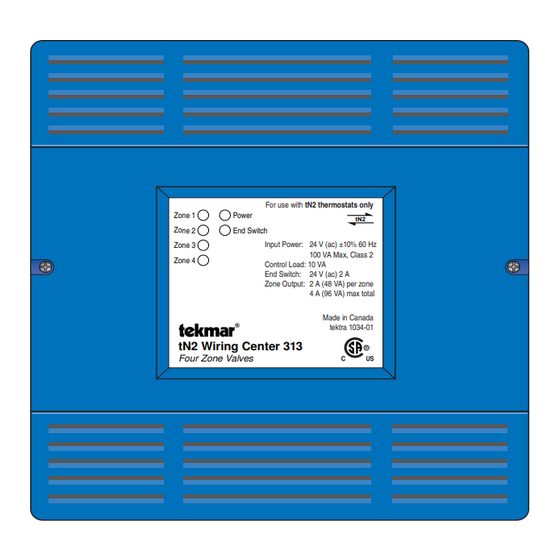
Power
End Switch
tN2 Wiring Center 313
Four Zone Valves
For use with tN2 thermostats only
tN2
Input Power: 24 V (ac) ±10% 60 Hz
100 VA Max, Class 2
Control Load: 10 VA
End Switch: 24 V (ac) 2 A
Zone Output: 2 A (48 VA) per zone
4 A (96 VA) max total
Made in Canada
tektra 1034-01
Features
•
Four 24 V (ac) powered zone outputs
•
For use with tekmarNet
•
Supports two-stage tekmarNet
•
tN4 expansion terminals
•
Isolated end switch
•
External diagnostic LEDs
•
CSA C US Certified for use in USA and Canada
Benefi ts
•
Simple, convenient wiring location
•
Compact enclosure for flexible installation
•
Reduce equipment cycling through the use of
tekmarNet
®
2 Thermostats
Note
•
Not for use with tekmarNet
1 of 12
D 313
11/10
Zoning
Replaces: 10/09
®
2 Thermostats
®
2 Thermostats
®
4 Thermostats
© 2010
D 313 - 11/10
Advertisement
Table of Contents

Related Manuals for Tekmar 313


Summary of Contents for Tekmar 313
- Page 1 Introduction ® The tekmarNet 2 (tN2) Wiring Center 313 is designed to operate up to four zone valves in a hydronic heating system. It can be mounted in the mechanical room or near a remote zone manifold, providing a convenient location to wire both thermostats and zone valves while only requiring two wires to be run back to the mechanical room.
-
Page 2: Table Of Contents
• 14 AWG solid wire (line voltage connections) • (2) wire nuts • tekmar 009 (24 V (ac) transformer) • 18 AWG LVT solid wire (low voltage connections) • Cable or conduit connectors Power Required -- -- - ------ - ----- - --- -- - - -- -- - - -- - -- -- - --- -- -- - --- -- - -- --- -- - -- --- -- - - -- --- -- -- - - -- - -- - - --- --- ----- ---- ----- ---- - - - - - - - - - - - - - - - - - - - - - - - - - - - - - - - - - - - - - - - - - - - - - - - - - - - - - - - - - - - - •... -
Page 3: Physical Dimensions
End Switch: 24 V (ac) 2 A (140 mm) Zone Output: 2 A (48 VA) per zone 4 A (96 VA) max total Made in Canada tektra 1034-01 tN2 Wiring Center 313 Four Zone Valves 7/8” Zone 1 Zone 2 Zone 3... -
Page 4: Sizing The Transformer
® 2 House Control (if applicable) Sizing the Transformer The control requires an external transformer. A tekmar The total power capacity of the power supply should be Transformer 009 (or 009K which includes a 4”x 4” electrical larger than the total load of all the devices connected box) can supply up to 40 VA, and includes an in-line fuse to the control. - Page 5 24 V (ac) to power a demand on a tekmar outdoor reset Zone Valves control. • Wire the zone valves to the C and Vlv terminals on the 313. • End switches on zone valves are not required when using the 313.
-
Page 6: Testing The Control Wiring
If a fault is suspected, contact your tekmar sales representative issues. In the event that the display is off, or the display is for assistance. -
Page 7: Applications
4 Expansion to House Control A313-1 Description: tN2 Wiring Center 313, four tekmarNet ® 2 Thermostats, and four zone valves wired into a tekmar tN2 House Control 400 which controls the boiler, primary pump and DHW pump. tekmarNet ® tekmarNet ®... - Page 8 Description: tN2 Wiring Center 313, four tekmarNet ® 2 Thermostats, and four zone valves wired into a powered boiler demand input on a device such as a tekmar Boiler Control 260 which controls the primary pump and DHW pump. tekmarNet ®...
- Page 9 End Switch (X-X) To Boiler Enable (T-T) A313-3 Description: tN2 Wiring Center 313, four tekmarNet ® 2 Thermostats, and four zone valves wired into the T-T terminals on the boiler to give an enable. The primary pump is controlled externally.
-
Page 10: User Interface
LED turns on. The switch remains closed as long as any as indicated by the LED. zone is calling for heat. This can provide a boiler demand to a tekmar reset control, or provide a boiler enable to a boiler’s TT terminals. © 2010... -
Page 11: Energy Saving Features
Check the wiring between the thermostat and the Wiring Center for open or short circuits. If the thermostat was intentionally removed, power the Wiring Center off for 10 seconds. 11 of 12 © 2010 D 313 - 11/10... -
Page 12: Technical Data
Representative. tekmar Control Systems Ltd., Canada, tekmar Control Systems, Inc., U.S.A. Head Offi ce: 5100 Silver Star Road, Vernon, B.C. Canada V1B 3K4, 250-545-7749, Fax. 250-545-0650 Web Site: www.tekmarcontrols.com Product design, software and literature are Copyright ©...
Need help?
Do you have a question about the 313 and is the answer not in the manual?
Questions and answers