Table of Contents
Advertisement
Quick Links
- Data Brochure
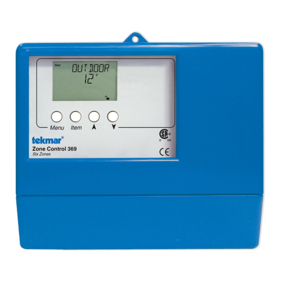
Zone Control 369
The Zone Control 369 is designed to control the temperature in up to six heating zones using Room Temperature Units (RTUs) or
indoor sensors. The 369 allows one stage heating zones, two stage heating zones, or a combination of one stage and two stage
heating zones. PID zoning logic allows for staggering and synchronization of multiple zones in order to minimize boiler short cycling.
The 369 is capable of operating a single cooling output and can provide automatic or manual heat / cool change over. When the 369
is used with a tekmar Reset or House Control, the 369 provides indoor temperature feedback that automatically adjusts the supply
water temperature in order to satisfy the zone with the highest heat load. A large Liquid Crystal Display (LCD) is incorporated in order
to view system status and operating information. The LCD and user key pad are used to set the control's adjustments and to monitor
zone running times, outdoor high and low temperatures, minimum zone temperatures, and many other useful items.
Additional features include:
• Control Schedule
• Individual Zone Schedules
• Optimum Start / Stop
• Cooling Control or Cooling Enable
• Manual Override
Zone Control 369
Six Zones
Do not apply power
!
Input
Timer
UnO
LR 58233 E150539
Input
tekmar Zone
Control
LR 58233 E150539
Output
tekmar Reset
Control
Input
Outdoor
Sensor
Included
OR
OR
OR
M
M
M
Output
Zone Valves or Zone Pumps
View
° F
Item
Menu
1
2
3
4
5
7
8
9
6
10
11
12
Zo
Zo
Com Out
Zn
Com
Zn
Zn
Com
Zn
Zn
Sw
In
Out
1
1-2
2
3
3-4
4
OR
OR
OR
M
M
M
Output
Cooling
• Slab Minimum and Slab Maximum Temperature Control
• Remote Display and Adjustment Capabilities
• Test Sequence to Ensure Proper Component Operation
• 115 V (ac) Power Supply
• CE and CSA C US Certified (approved to applicable UL standards)
INSTALLATION CATEGORY II
Made in Canada by
tekmar Control Systems Ltd.
C
US
Power:
Relays:
Signal wiring must be rated at least 300V.
!
16
17
18
19
13
14
15
20 21 22 23 24
Cooling Sys
Power
Com tN1
Com
Zn
tN1
Indr
5
5-6
6
Pmp
1
2
2
L
N
Output
Input
System
115 V (ac)
Pump
Power
Supply
1 of 32
Setback
off
not testing
red
testing
red
testing paused
None
Test
Lithium Battery CR1620
POS (+) up
Press here
on battery to
remove it.
WARNING: Battery may explode
or cause burns if disassembled,
recharged or exposed to fire or
high temperatures.
115 V 50/60 Hz 600 VA
230 V (ac) 5 A
Do not apply power
!
25
26
27
28
29
30
31
Com
tN1
tN1
Indr
Com
tN1/2
tN1
Indr
3
4
4
5
6
6
Menu
Item
Menu
Item
Input
Input
Input
Room
Room
Indoor
Temperatue
Temperatue
Sensor
Unit (RTU)
Unit (RTU)
D 369
01/09
01/09
Input
Indoor
Sensor
70
Input
Room
Temperatue
Menu
Item
Unit (RTU)
Input
Remote
WWSD
Display
Menu
Item
Module
or
Input
Room
Temperatue
Menu
Item
Unit (RTU)
Input
Indoor
Sensor
Input
Room
Temperatue
Menu
Item
Unit (RTU)
Input
Room
Temperatue
Menu
Item
Unit (RTU)
70
Copyright © D 369 -10/00
- 01/09
Advertisement
Table of Contents

Subscribe to Our Youtube Channel
Related Manuals for Tekmar Zone Control 369


Summary of Contents for Tekmar Zone Control 369
- Page 1 01/09 The Zone Control 369 is designed to control the temperature in up to six heating zones using Room Temperature Units (RTUs) or indoor sensors. The 369 allows one stage heating zones, two stage heating zones, or a combination of one stage and two stage heating zones.
-
Page 2: Table Of Contents
How To Use The Data Brochure This brochure is organized into four main sections. They are: 1) Sequence of Operation , 2) Installation , 3) Control Settings , and 4) Troubleshooting . The Sequence of Operation has four subsections. We recommend reading each subsection of the Sequence of Operation , as each one contains important information on the overall operation of the control. - Page 3 - 01/09 MENU FIELD The 369 has a number of menus used to monitor system status and adjust settings in the control. The current menu will be displayed in the left hand side of the display. View Menu View The View menu is used to view the outdoor temperature and zone temperatures. °...
-
Page 4: Description Of Display Elements
- 01/09 Display Item Field Number Field Displays an abbreviated name Displays the current value of of the selected item the selected item View Adjust Monitor ° F ° C Time Menu Field min hr Schd D i s p l a y s t h e Misc current menu... -
Page 5: Sequence Of Operation
In order for Zone Control synchronization to work properly, the cycle length on each Zone Control must be equal. Note: If a Zone Control 367/ 368 or House Control 370 / 371 is used with a Zone Control 369, the HEAT CYC adjustment in the 369 should be set to 15 minutes. - Page 6 The 369 can provide indoor temperature feedback to a tekmar Reset Control. When multiple Zone Controls are used, each zone control uses its Zo Out output to sequentially pass the information to the tekmar Reset Control. The ZO OUT item displayed in the view menu represents the target from the zone with the highest heat requirement.
-
Page 7: Section B: Cooling
Section B1: General Cooling GENERAL COOLING The Zone Control 369 is capable of operating a single cooling group to provide either cooling enable (ENBL) Adjust or cooling control (CTRL). This is an adjustable item through the COOL MOD setting in the Control Adjust menu of the control. - Page 8 - 01/09 HEAT / COOL CHANGEOVER The changeover between heating and cooling is based on whether or not a display RTU is connected to zone 6 ( tN1 6 ). If a display RTU is connected to zone 6 ( tN1 6 ), the changeover between heating and cooling is selected at RTU 6. A pointer in the lower right hand display of the RTU indicates that this RTU is the designated heat / cool RTU.
-
Page 9: Section C: Setback (Unoccupied)
- 01/09 Section C: UnOccupied SETBACK (UNOCCUPIED) To provide greater energy savings, the 369 can lower the building temperature at night or when the building is unoccupied. The 369 has a built-in clock which allows for heating and cooling setback capabilities. As an option, an external timer may be connected to provide a separate setback signal. - Page 10 - 01/09 SCHEDULE OVERRIDES The 369 has a number of setback overrides that are selected through the schedule (Schd) menu. A system override and a zone override are available. Any time an override is in effect, the Ovr segment is displayed in the appropriate LCD. Schd System Override (OVERRIDE) UnOcc...
-
Page 11: Section D: Tn 1 / 2 Devices
Remote indoor sensors can be connected to the 063 to average the air temperature read- ing. Typically, multiple remote sensors are used in large open areas in a building to get an average indoor air temperature. Any type of tekmar 10K sensor can be connected to the input(s) on the 063. -
Page 12: Installation
STEP ONE GETTING READY Check the contents of this package. If any of the contents listed are missing or damaged, please contact your wholesaler or tekmar sales representative for assistance. Type 369 includes: One Zone Control 369, One Outdoor Sensor 070, Data Brochures D 369, D 070, D 001, Application Brochure A 369, User Brochure U 369. -
Page 13: Electrical Connections
- 01/09 STEP FOUR ELECTRICAL CONNECTIONS TO THE CONTROL The installer should test to confirm that no voltage is present at any of the wires. Push the control into the base and slide it down until it snaps firmly into place. Powered Input Connections 115 V (ac) Power Connect the 115 V (ac) power supply to the Power L and Power N... - Page 14 369 and continue this process for each additional 369. The Zo Out terminal on the last 369 in the chain can be connected to the Zo In terminal on a tekmar House Control or 10K terminal on a tekmar Reset Control.
-
Page 15: Testing The Wiring
- 01/09 Zone 6 ( tN1 6 or Indr 6 ) Connect the Com terminal from the RTU to the Com terminal (28) on the 369. Connect the tN1 terminal from the RTU to the tN1 6 terminal (30) on the 369. If an indoor sensor is used, connect the two wires from the sensor to the Com and Indr 6 terminals (28 and 31). - Page 16 - 01/09 Test The Power Supply Make sure exposed wires and bare terminals are not in contact with 103.5 to 126.5 V (ac) other wires or grounded surfaces. Turn on the power and measure the voltage between the Power L and Power N terminals (18 and 19) using an AC voltmeter.
-
Page 17: Dip Switch Settings
LOCK / UNLOCK The Lock / Unlock DIP switch is used to lock and unlock the access level of the control and tekmar Net ™ tN1 / tN2 device(s). Once locked, access levels cannot be changed. To determine if the control is currently locked or unlocked, a small segment representing a padlock is viewed in the bottom right hand corner of the display. -
Page 18: Control Settings
- 01/09 369 View Menu (1 of 1) Access Level Item Field Description Range Current outdoor air temperature as measured by the outdoor – – –, -67 to 149°F sensor. This is also the default display for the control. (-55 to 65°C) –... - Page 19 - 01/09 369 Control Adjust Menu (2 of 2) Access Level Actual Item Field Description Range Setting The time the heating zones assigned to the cooling group must be off before cooling operation 0:10 to 3:00 hr is allowed. Default = 0:30 hr COOL MOD ≠...
-
Page 20: Monitor Menu
- 01/09 369 Zone Adjust Menu (2 of 2) Access Level Actual Item Field Description Range Setting Desired room air temperature during an 35 to 100°F occupied period. (2 to 38°C) (Indoor sensor is present.) Default = 70°F (21°C) Desired room air temperature during an 35 to 100°F unoccupied period. -
Page 21: Time Menu
- 01/09 369 Monitor Menu (2 of 2) Note: To clear the recorded information in the specific item field, press and hold L and M. Access Level Item Field Description Range The total number of Zn 5 relay running hours since this item 0 to 9999 hr was last cleared. -
Page 22: Schedule Menu
- 01/09 369 Schd (Schedule) Menu (1 of 1) Access Level Item Field Description Range NONE, TMPY Occ Ovr, The type of setback override that is in effect for all PERM Occ Ovr, TMPY schedules. UnOcc Ovr, PERM UnOcc Ovr, AWAY DIP switch = Setback AWAY is available even if DIP switch ≠... -
Page 23: Miscellaneous Menu
DIP switch = Unlock Default = INST Room Temperature Units (RTUs) 062 and 063 A display RTU may be connected to the Zone Control 369 in order to provide the control with indoor temperature View ° F feedback for the heating system (Refer to Essay E 002). When using display RTUs, several items related to the UnOcc 1 system are no longer available in the control’s User Interface. - Page 24 - 01/09 369 RTU Adjust Menu (1 of 1) Access Level Item Field Description Range OFF, HEAT The operating mode for this zone. Default = HEAT RTU 1 to RTU 5 or RTU 6 if COOL MOD = NONE OFF, HEAT, AUTO, The operating mode for this zone.
- Page 25 - 01/09 369 RTU Monitor Menu (1 of 1) Note: To clear the recorded information in the specific item field, press and hold L and M. Access Level Item Field Description Range -67 to 140°F The highest outdoor air temperature recorded since (-55 to 60°C) this item was last cleared.
- Page 26 - 01/09 369 RTU Schd (Schedule) Menu (1 of 1) Access Level Item Field Description Range NONE, TMPY Occ Ovr, The type of setback override that is in effect for all PERM Occ Ovr, TMPY schedules. UnOcc Ovr, PERM DIP switch = Setback UnOcc Ovr, AWAY Ovr AWAY is available even if DIP switch ≠...
-
Page 27: Testing And Troubleshooting
Displays which tn1 terminal on the 369 this RTU is RTU1. . . RTU6 connected to. Testing the Control The Zone Control 369 has a built in test routine which is used to test the not testing main control functions. The 369 continually monitors the sensors and testing displays an error message whenever a fault is found. - Page 28 MAX HEAT (MAX HEAT) The Zone Control 369 has a function called Max Heat. In this mode, the 369 sets all RTU room temperature settings to 75°F (24°C) and turns on the required contacts. The RTU room setting may be adjusted to turn on or off the required zone without delay. The control continues to operate in this mode for up to 24 hours or until either the Item , Menu or Test button is pressed.
-
Page 29: Error Messages
- 01/09 Isolate the problem between the control and the system. Now that the sequence of operation is known Isolate the and the system is sketched, is the control operating the proper pumps and valves at the correct times? Problem Is the control receiving the correct signals from the system as to when it should be operating? Are the proper items selected in the menus of the control for the device that is to be operated? Test the contacts, voltages and sensors. - Page 30 The error messages listed below for 1 tN1 will be the same for 2 tN1, 3 tN1, 4 tN1, 5 tN1 and 6 tN1. An incorrect device has been connected to the tekmar Net™ tN1 1 input terminal. Once the problem has been corrected, press either the Menu or Item button to clear the error message from the control.
- Page 31 - 01/09 369 Error Messages (3 of 3) The error messages listed below for RTU 1 will be the same for RTU 2, RTU 3, RTU 4, RTU 5 and RTU 6. Error Displayed Description of Error The control is no longer able to read the information that is coming from RTU 1. Reconnect RTU 1 and press either the Menu or Item button to clear the error.
-
Page 32: Technical Data
This warranty is in lieu of all other warranties, express or implied, which the Governing Law (being the law of British Columbia) allows parties to contrac- The liability of tekmar under this warranty shall be limited to, at tekmar's sole dis- tually exclude, including, without limitation, warranties of merchantability, cretion: the cost of parts and labor provided by tekmar to repair defects in materials fitness for a particular purpose, durability or description of the product, its...
Need help?
Do you have a question about the Zone Control 369 and is the answer not in the manual?
Questions and answers