Table of Contents
Advertisement
Quick Links
- Data Brochure
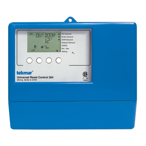
Universal Reset Control 364
The Universal Reset Control 364 is designed to maximize the comfort and efficiency provided by a hydronic heating system. The
control automatically adjusts the boiler and mixed loop water temperatures that are delivered to the heating system by using outdoor
reset. For a mixing device, the 364 can use either a variable speed injection pump or a floating action mixing valve. The mixed water
temperature can be used to supply either a space heating system or a single zone snow melting system. The 364 is capable of
controlling an indirect Domestic Hot Water (DHW) storage tank and / or a setpoint load. The temperature of individual zones can be
controlled by connecting either a conventional thermostat system or a tekmar zone control to the 364. A large Liquid Crystal Display
(LCD) is incorporated in order to view system status and operating information.
Additional features include:
• Warm Weather Shut Down (WWSD)
• Manual Override
• Optional DHW Priority
• Remote Display and Adjustment Capabilities
Input
Universal Reset Control 364
Mix
Demand
Mixing, Boiler & DHW
signal
Input
Boiler
Demand
signal
Input
Setpoint
or DHW
Demand
signal
Input
120 V (ac)
Power
Supply
Output
Primary
Pump
Output
Boiler
System
Pump
Output
Mixing
System
Pump
Output
DHW Pump
DHW Valve
Menu
Item
1
2 3
4
5
6
7
8
9
10 11 12 13 14 15
Mix
Boil
Com
Setp/
Power
Prim
Boil Sys
Mix Sys
Demand
Dem
Dem
DHW
N
L
P1
Pmp P2
Pmp P3
M
Output
Output
Var. Speed
OR
Boiler
Driven Pump
• Test Sequence to Ensure Proper Component Operation
• 120 V (ac) Power Supply
• CSA C US Certified (approved to applicable UL standards)
Mix Demand
Boiler Demand
DHW Demand
Setpoint Demand
WWSD
Min / Max
Melting
Made in Canada by
tekmar Control Systems Ltd.
tektra 928-01
Power
Relays
Var. Pump
Demands
158033
Signal wiring must be rated at least 300 V.
Do not apply power
Do not apply power
16 17
18
19
20
21
22
23
24
DHW
Boiler
Pwr
Opn
Cls/
Com
Mix
Mix
Mix
Com
Pmp/Vlv
Mix
Var
10K
Ret
Sup
M
OR
Output
tekmar Zone Control,
Mixing Valve &
Slab Sensor, or Indoor Sensor
Actuating Motor
for mixing zones
1 of 36
Snow Melting
Mixing Reset
Test
off
not testing
red
testing
red
testing paused
For maximum heat,
press and hold Test
button for 3 seconds.
120 V ± 10% 50/60 Hz 1300 VA
240 V (ac) 5 A 1/3 hp, pilot duty 240 VA
240 V (ac) 2.4 A 1/6 hp, fuse T2.5 A 250 V
20 to 260 V (ac) 2 VA
25
26
27
28
29
30
Boil
Boil
Com
DHW
Out
tN2
Zo In
OR
70
OR
Input
Input
Universal Sensor
Optional
© 2001
D 364
07/01
OR
8
Input
Remote Start/
Stop Module or
Remote Display
Module (RDM)
Input
Outdoor
Sensor
Included
Input
Universal Sensor
Optional
Input
Universal Sensor
Included
Input
Zone
Control
for boiler
zones
Input
Universal Sensor
Included
D 364 - 07/01
Advertisement
Table of Contents

Related Manuals for Tekmar 364


Summary of Contents for Tekmar 364
- Page 1 For a mixing device, the 364 can use either a variable speed injection pump or a floating action mixing valve. The mixed water temperature can be used to supply either a space heating system or a single zone snow melting system.
-
Page 2: Table Of Contents
User Interface The 364 uses a Liquid Crystal Display (LCD) as the method of supplying information. You use the LCD in order to setup and monitor the operation of your system. The 364 has four push buttons (Menu, Item, L, M) for selecting and adjusting settings. As you program your control, record your settings in the Adjust menu table which is found in the second half of this brochure. -
Page 3: Description Of Display Elements
- Warning Symbol: Indicates presence of hazards which can cause severe personal injury, death or substantial property damage if ignored. - Double insulated INSTALLATION - Local level, appliances CATEGORY II 3 of 36 © 2001 D 364 - 07/01... -
Page 4: Sequence Of Operation
POWERING UP THE CONTROL When the Universal Reset Control 364 is powered up, the control displays the control type number in the LCD for 2 seconds. Next, the software version is displayed for 2 seconds. Finally, the control enters into the normal operating mode and the LCD defaults to displaying the current outdoor air temperature. -
Page 5: Section B: Boiler Zones
10 seconds. This minimizes the possibility of a pump or valve seizing during a long period of inactivity. In the case where a mixing valve is being used as the mixing device, the 364 ensures that the valve operates over its entire range at least once each exercising period. -
Page 6: Section C: Domestic Hot Water
A tekmar zone control can be used to control the temperature in the boiler zones that are connected to the boiler system pump (P2). The tekmar zone control is connected to the 364 using the Boil Zo In terminal and Com terminal (25 and 24). The zone control provides its own internal boiler demand to the 364. - Page 7 It is often desirable to limit or even stop the flow of heat to the heating system when the DHW tank calls for heat. This allows for faster recovery of the DHW tank. The 364 has a number of features that it can use when dealing with DHW priority. The features available depend on the type of DHW device that is being used and the type of DHW demand the control receives.
- Page 8 RET or NONE. On a call for DHW, the 364 provides DHW priority by backing off the mixing device and by shutting off the boiler system pump (P2) for a period of time. This time is based on the outdoor air temperature as described in the DHW Priority Override section. If the DHW demand is not satisfied within the allotted time, the boiler shuts off and the boiler’s heat is purged into the DHW tank.
-
Page 9: Section D: Mixing Zones
Section C4: Setpoint The 364 can handle loads which are high temperature loads connected to the boiler loop that are not heating loads or DHW. For this feature to be available, the Boil SENS item must be set to SUP and either a DHW sensor must be used or the DHW THRU item is set to NONE. - Page 10 The 364 is capable of providing boiler protection from cold mixing system return water temperatures. If the boiler water temperature is cooler than the Boil MIN setting while the boiler is firing, the 364 reduces the output from the mixing device. This limits the amount of cool return water to the boiler and allows the boiler water temperature to recover.
- Page 11 240 V (ac) across the Mix Demand terminals (1 and 2). Once voltage is applied, the Mix Demand pointer is displayed in the LCD. If the 364 is not in WWSD, the 364 closes the Mix Sys Pmp P3 contact. The mixing system pump segment is displayed in the LCD. The 364 calculates a MIX TRG temperature based on the outdoor air temperature and set- tings.
-
Page 12: Section E: Snow Melting
At low temperatures, the glycol solutions used in the snow melting systems become very viscous and difficult to pump. In order to overcome this condition during a cold start of a snow melting system, the 364 is allowed to exceed the ∆ T MAX setting for a period of time in order to warm the glycol solution. - Page 13 The 364 can only provide boiler protection if the Boil SENS item is set to SUP or RET. The 364 can not provide boiler protection if the Boil SENS item is set to NONE.
- Page 14 MELTING MODE (MELTING) The Universal Reset Control 364 is a manual snow melting control. In order for the snow melting system to be started, one of the three methods described in section E4 must be used. When the control is in the melting mode, the Melting pointer is visible in the View menu and either EXT, INF or a running time can be read when viewing the SNOWMELT item in the View menu.
-
Page 15: Section F: Boiler Operation
The Boil MIN is the lowest water temperature that the control is allowed to use as a Boil TRG temperature. During mild conditions, if the 364 calculates a Boil TRG temperature that is below the Boil MIN setting, the Boil TRG temperature is adjusted to at least the Boil MIN setting. -
Page 16: Installation
BOILER PURGE (PURGE P1) After all of the demands are satisfied, the 364 continues to operate the primary pump (P1, terminal 8) for a period of time. The length of time that the primary pump continues to run is adjustable (PURGE P1). This setting allows any excess heat to be purged out of the boiler after the burner is shut off. - Page 17 If a Remote Start / Stop Module 039 is used, install the module according to the installation instructions in the Data Brochure D 039 and run the wiring back to the control. • If a tekmar Zone Control is used, run the wires from the Zone Control to the 364. Refer to instructions supplied with Zone Control. •...
- Page 18 The Prim P1 output terminal (8) on the 364 is a powered output. When the relay in 120 V (ac) the 364 closes, 120 V (ac) is provided to the Prim P1 terminal (8) from the Power L terminal (7). To operate the primary pump, connect one side of the primary pump circuit to terminal 8 and the second side of the pump circuit to the neutral (N) side of the 120 V (ac) power supply.
- Page 19 If an external tekmar zone control is used for control of mixing zones, connect the wire from the Com Sen terminal on the zone control to the Com terminal (20) on the 364. Connect the Zo Out ter- tekmar 364 Zone Control minal on the zone control to the Mix 10K terminal (21) on the 364.
- Page 20 20 and 260 V (ac) at the terminals. When the setpoint demand device is off, you should measure less than 5 V (ac). © 2001 D 364 - 07/01 20 of 36...
- Page 21 If it does not, check the wiring between the terminals and the actuating motor. Refer to any installation or troubleshooting information supplied with the motor. If the motor closes correctly, turn off the power to the circuit and remove the jumper. 21 of 36 © 2001 D 364 - 07/01...
-
Page 22: Dip Switch Settings
LOCK / UNLOCK (FACTORY SETTING IS UNLOCK) The Lock / Unlock DIP switch is used to lock and unlock the access level of the control and tekmar Net tN2 device. Once locked, access levels cannot be changed. To determine if the control is currently locked or unlocked, a small segment representing a padlock is viewed in the bottom right hand corner of the display. -
Page 23: Control Settings
Access Levels The Universal Reset Control 364 comes with four Access Level settings. These Access Levels restrict the number of Menus, Items and Adjustments that can be accessed by the user. The four access levels are Limited (LTD), User (USER), Installer (INST) and Advanced (ADV). -
Page 24: Adjust Menu
Measured room air temperature at the indoor sensor. -58 to 167°F MIX 10K = INDR (-50 to 75°C) This is the signal that is being received from a tekmar ---, 35 to 110°F Zone Control that is operating the mixing zones. (2 to 43°C) MIX 10K = ZOIN Target slab temperature. - Page 25 364 View Menu (2 of 2) Access Level Item Field Description Range Target boiler supply is the temperature the control is cur- ---, 1 to 255°F rently trying to maintain at the boiler sensor ±1/2 of the (-17 to 124°C) differential.
- Page 26 364 Adjust Menu (2 of 5) Access Level Actual Item Field Description Range Setting 10 to 70°F, OFF The maximum ∆ T for the snow melting slab. (-6 to 39°C, OFF) DIP switch = Snow Melting Default = 40°F (22°C) OFF, -30 to 50°F...
- Page 27 364 Adjust Menu (3 of 5) Access Level Actual Item Field Description Range Setting 80 to 210°F, OFF The maximum supply temperature for the (27 to 99°C, OFF) mixing system. Default = 140°F (60°C) -60 to 50°F The design outdoor air temperature used in the (-51 to 10°C)
-
Page 28: Miscellaneous Menu
364 Adjust Menu (4 of 5) Access Level Actual Item Field Description Range Setting The time delay that the control can expect between the time the boiler contact closes and 0:00 to 3:00 min Default = 0:10 min the burner fires. -
Page 29: Testing And Troubleshooting
The frequency with which the control will exer- 30 to 240 hr cise the pumps and valves that are operated by Default = 70 hr the control. 364 Misc (Miscellaneous) Menu (1 of 1) Access Level Item Field Description Range The units of measure that all of the temperatures are to be °F, °C... - Page 30 The Universal Reset Control 364 has a built-in test routine which is used to test the main control functions. The 364 continually moni- tors the sensors and displays an error message whenever a fault is found. See the following pages for a list of the 364’s error mes- sages and possible causes.
-
Page 31: Error Messages
Allow the system and the control to operate over a known period System of time and then record the Monitor items. Use the information to help diagnose any remaining problems. 31 of 36 © 2001 D 364 - 07/01... - Page 32 Menu or Item button to clear the error message from the control. A short circuit has been read between the tekmar Net (tN2) and a Com terminal on the control. Either the wires leading to the tekmar Net (tN2) device are shorted or the polarity of the wires is reversed.
- Page 33 364 Error Messages (2 of 3) Error Displayed Description of Error The control is no longer able to read the mix return sensor due to a short circuit. The control continues to operate without ∆ T protection of the slab. Locate and repair the problem as described in the Data Brochure D 070.
- Page 34 364 Error Messages (3 of 3) Error Displayed Description of Error The control is no longer able to read the DHW sensor due to a short circuit. In this case, the control ceases DHW operation. Locate and repair the problem as described in the Data Brochure D 070. To clear the error message from the control after the sensor has been repaired, press either the Menu or Item button.
- Page 35 Notes 35 of 36 © 2001 D 364 - 07/01...
-
Page 36: Technical Data
Technical Data Universal Reset Control 364 Mixing, Boiler & DHW Literature — D 364, A 364’s, D 070, D 001, U 364, E 021, E 003 Control — Microprocessor PID control; This is not a safety (limit) control Packaged weight —...
Need help?
Do you have a question about the 364 and is the answer not in the manual?
Questions and answers