Table of Contents
Advertisement
Quick Links
Advertisement
Table of Contents

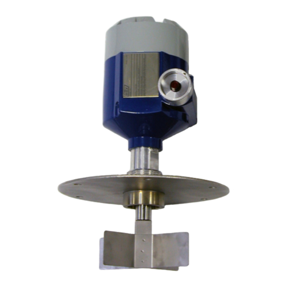
Summary of Contents for K-TEK KP
-
Page 2: Table Of Contents
III. REPLACEMENT PARTS ................... 11 IV. INTERNAL ASSEMBLY REPLACEMENT ..............12 A. Old Internal Assembly Removal ..............12 B. New Internal Assembly Installation ..............13 V. STANDARD CONFIGURATIONS ................15 VI. WARRANTY STATEMENT ..................16 KP-0200-1 Rev f (10-2010) DCN0536... - Page 3 - DIP, CLII, DIV1, GP EFG, CLIII - T6 @ 76°C (170°F) APPROVED CL I, Zn 1 &2, AEx d IIB Ex d IIB MADE IN USA T6 @ 76°C (170°F) T6 @ 76°C (170°F) TAG0044 NEMA 4 TYPE 4 KP-0200-1 Rev f (10-2010) DCN0536...
-
Page 4: Installation
Drill & Tap (6 each) For most of our competitors. 1/4 –20 Bolt Threads 2. Replacement of competi- Equally Spaced tors’ mounting plate is not re- quired! 7.0 inch Diameter Bolt Circle KP-0200-1 Rev f (10-2010) DCN0536... - Page 5 (if possible) Figure 1 Paddle Pin Removal: Use a 0.125” diameter center punch or a 0.125” wide flat screwdriver to drive the paddle pin out of the paddle shaft for paddle removal. KP-0200-1 Rev f (10-2010) DCN0536...
-
Page 6: Side Bin Wall Mounting
(1-1/8”) below the bottom of the housing only. DO NOT tighten the housing into the cou- pling by turning the housing itself. 1/8" GASKET RECOMMENDED BIN WALL 3/4" CONDUIT ENTRY MOUNTING FLANGE (MOUNTING BOLTS NOT SHOWN) HALF PIPE COUPLING FLEX COUPLING (OPTIONAL) PADDLE FIGURE 2 Figure 2 KP-0200-1 Rev f (10-2010) DCN0536... -
Page 7: Top Bin Wall Mounting
3/4" CONDUIT ENTRY MOUNTING FLANGE (MOUNTING BOLTS 1/8" GASKET NOT SHOWN) RECOMMENDED BIN WALL FULL PIPE COUPLING FLEX COUPLING (OPTIONAL) EXTENDED SHAFT GUARD (OPTIONAL) SHAFT ADAPTER FOR EXTENDED SHAFT PADDLE EXTENDED SHAFT Figure 3 FIGURE 3 KP-0200-1 Rev f (10-2010) DCN0536... -
Page 8: Wiring Connections
9. To make wiring connections to the switches, loosen the left-most switch mounting screw per Figure 4 a few turns and hinge up the switch bracket assembly for access to the switch terminals. Figure 4 KP-0200-1 Rev f (10-2010) DCN0536... - Page 9 All efforts should be taken to run the field wiring as shown here. 13. After all wiring terminations are made, screw the cover back on and tighten. KP-0200-1 Rev f (10-2010) DCN0536...
- Page 10 DO NOT RUN WIRING WITH EXTRA LENGTHS DO NOT "STUFF" EXTRA WIRING AGAINST SWITCH ASSEMBLY MANUALLY EXERCISE MOTOR BRACKET ROTATION TO ENSURE FREE, UNRESTRICTED MOTION AFTER WIRING CONNECTIONS HAVE BEEN MADE TO FIELD DEVICE i.e. PUMP, CONVEYER, ETC. Figure 8 KP-0200-1 Rev f (10-2010) DCN0536...
-
Page 11: Operation
Replacement Top-Bin Mounting Plate with full coupling with Rubber Gasket MEC2335 1/8” Rubber Gasket for Mounting Plate ELESWTLM-20-A 20 AMP SPDT Micro Switch KPL2 120 VAC - Indicating Lamp (General Purpose Only) KPL3 240 VAC - Indicating Lamp (General Purpose Only) KP-0200-1 Rev f (10-2010) DCN0536... -
Page 12: Internal Assembly Replacement
Figure 9. Retain the screws for re-installation. 7. Lift out the switch assembly from the housing. REMOVE REMOVE Figure 9 KP-0200-1 Rev f (10-2010) DCN0536... -
Page 13: New Internal Assembly Installation
Note: DO NOT TIGHTEN THE LOWER MOUNTING SCREWS IF THE SHAFT IS NOT PROPERLY COU- PLED. THE ASSEMBLY WILL BE DAMAGED AND WILL NOT OPERATE AS DESIGNED. KP-0200-1 Rev f (10-2010) DCN0536... - Page 14 8. Re-install the paddle switch to its intended final location. Re-connect the wiring connections to the switches as required (See Figures 5-8). 9. Screw on the cover until fully tightened. The device can then be powered and brought back into service. KP-0200-1 Rev f (10-2010) DCN0536...
-
Page 15: Standard Configurations
3. Combine the two selections to determine the abbreviated model order number. (example KP/2A/1) 4. For FM and CSA Explosion Proof units add /FM to model number. (Example: KP/2A/1/FM) 5. For ATEX approved unit add /CE to model number. (Example: KP/2A/1/CE) For optional indicator light (general purpose only), add /L2 (120VAC) or /L3 (240VAC). -
Page 16: Warranty Statement
K-TEK will repair or replace, at K-TEK’s election, defective items which are returned to K-TEK by the original purchaser within the period specified above from the shipment date of the item and which is found, upon examination by K-TEK, to its satisfaction, to contain defects in materials or workmanship which arose only under normal use and service and which were not the result of either alterations, misuse, abuse, improper or inadequate adjustments, applications or servicing of the product. - Page 17 KP-0200-1 Rev f (10-2010) DCN0536...
- Page 18 KP-0200-1 Rev f (10-2010) DCN0536...
- Page 19 KP-0200-1 Rev f (10-2010) DCN0536...
- Page 20 KP-0200-1 Rev f (10-2010) DCN0536...


Need help?
Do you have a question about the KP and is the answer not in the manual?
Questions and answers