Table of Contents
Advertisement
Advertisement
Table of Contents

Related Manuals for K-TEK RS80


Summary of Contents for K-TEK RS80
- Page 1 RS80 RS85...
-
Page 2: Table Of Contents
Setup ........................9 3.1 Accessing Setup Adjustments ................9 3.2 Density - Setpoint Adjustment - High (RS80 only) .......... 10 3.3 Density - Setpoint Adjustment - Low (RS80 only) ........... 11 3.4 Fail Safe / Relay Operation (RS80/RS85) ............12 3.5 Fault Mode ..................... -
Page 3: Introduction
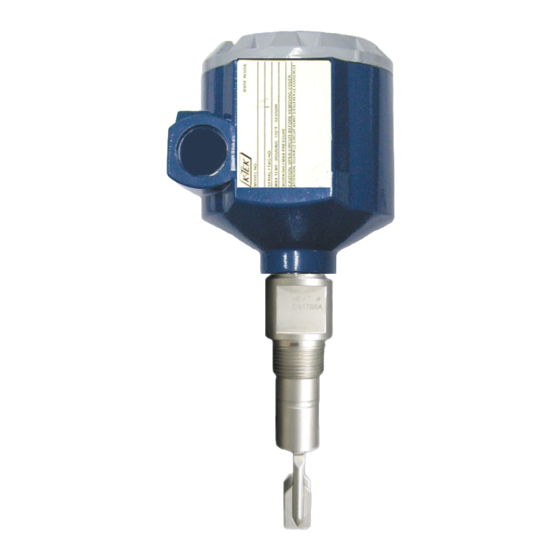
Its rugged construction allows it to withstand the rigors of just about any industrial environ- ment. The Resonator switch is available in two different models: (1) RS80 - base model or (2) RS85 - multi-options model. -
Page 4: Sample Applications
The Resonator™ (RS85 only) is also available with Teflon coatings or alloy wetted parts for use in corrosive fluid and sticky applications. Resonator dual compartment housing and custom insertion length Resonator switches Resonator switches mounted in External mounted in KM26 Chamber Magnetic Level Gauge Empty Pipe Detection Level in Vertical Pipe RS80-0200-1 Rev d (10-2010) DCN0533... -
Page 5: Installation
Switchpoints on the sensor depend on the mounting position. Because the Resonator requires no calibration, the switchpoint is determined by the position of the tuning fork. Note: When used in extremely light liquids (liquefied gas), select the low density Setpoint adjustment. Side Mounted Top Mounted Bottom Mounted RS80-0200-1 Rev d (10-2010) DCN0533... - Page 6 A short extended probe length (up to 20 inches) can be mounted in any orientation. A Resonator with an extended probe length over 20 inches (up to 120”) must be mounted vertically. RS80-0200-1 Rev d (10-2010) DCN0533...
- Page 7 Note: To avoid blockage of the flowing material, ensure narrow edge of forks is parallel with pipe walls. To maintain optimum performance in flow or no flow applica- tions, the liquids should have low viscosities and low flow veloci- ties. Empty Pipe Detection RS80-0200-1 Rev d (10-2010) DCN0533...
-
Page 8: Integral And Remote Units
Due to the extremely wide range of control and/or alarm applications in which the unit may be used, it is not possible to show all conceivable wiring diagrams. Consult your representative or K-TEK factory if further assistance is needed. 2.3 Caution... -
Page 9: Setup
On RS80 Forks, install and power up the unit with no liquid touching the fork. Place a magnet on the X of the label on the housing or press S1 and S2 buttons of the electronics module and hold while a sequence of red and green lights display ending with a single green light. -
Page 10: Density - Setpoint Adjustment - High (Rs80 Only)
3.2 Density - Setpoint Adjustment - High (RS80 only) The default density setting of the RS80 is High. This means that the switch is set to detect fluids with a specific grav- ity of 0.8 and above. The Resonator can be configured to change the default settings externally with a magnet or internally with the pushbuttons inside the enclosure. -
Page 11: Density - Setpoint Adjustment - Low (Rs80 Only)
3.3 Density - Setpoint Adjustment - Low (RS80 only) The Resonator can be configured to change the default settings externally with a magnet or internally with the pushbuttons inside the enclosure. To set the switch for detecting fluids with a specific gravity of 0.8 and below follow the steps below. -
Page 12: Fail Safe / Relay Operation (Rs80/Rs85)
3.4 Fail Safe / Relay Operation (RS80 and RS85) A fail safe relay operation is used to let the user know that the switch has power. This means the relays will be ener- gized when the level is below the switch (dry fork) and de-energized when the level is above the switch (wet fork). -
Page 13: Troubleshooting
Mount Resonator Switch in a bypass line conditions, foaming liquid Extreme RFI Use shielded cable Sporadic faulty switching Extreme vibration Decouple, damp, turn fork 90° Water in housing Screw cover and cable gland tight Output overloaded Reduce load: (Cable) capacitance RS80-0200-1 Rev d (10-2010) DCN0533... -
Page 14: Appendix A (Rs85 Only Setup)
5.1 Density Adjustment - Precise Density Setpoint Adjustment (RS85 only) While the RS80 (base model) should be able to handle 80% of all liquid level applications, there are cases when the process requires more flexibility due to extreme buildup, turbulence, high viscosity or sticky process products. These applications require the use of the RS85 (multi-options). - Page 15 Table 6 - Setpoint Adjustment While Wet OPERATION LED 1 LED 2 Normal GREEN OR RED X for over 6 seconds GREEN GREEN or RED Figure 14 Figure 13 Figure 15 Figure 16 RS80-0200-1 Rev d (10-2010) DCN0533...
-
Page 16: Time Delay (Rs85 Only)
0 seconds, LED1 will change color when the switch point has been reached (See Figure 18). The relays will respond after the elapsed Time Delay on both energized and de-energized actions. Figure 17 Figure 18 RS80-0200-1 Rev d (10-2010) DCN0533... -
Page 17: Factory Default Settings / Reset (Rs85 Only)
GREEN GREEN Remove the magnet The RS80/85 will be restored to normal operation with the default settings. The Resonance Frequency at the mo- ment the magnet is removed will become the dry setpoint. (See Figure 19 and 20) Figure 20... -
Page 18: Loop Powered Alarm (Rs85 Only)
Releasing the pushbutton when LED2 is green will set loop power alarm at 4 mA. Table 10 - Loop Powered Alarm OPERATION LED 1 LED 2 Normal GREEN OR RED S2 for more than 6 seconds Remove the magnet GREEN = LOW RED = HIGH Figure 22 Figure 21 RS80-0200-1 Rev d (10-2010) DCN0533... -
Page 19: Fm Approval On 120Vac Or 240Vac Installations
240 VAC, the crimped pin terminals provided must be used for all electrical connections inside of the housing. Install crimp pin terminals to the end of stranded type wires using a crimpling tool before installing wires in terminal block. RS80-0200-1 Rev d (10-2010) DCN0533... -
Page 20: Remote Assembly
Probe Enclosure Terminal Wiring AWG) Normally Open 2 Normally Closed 2 Common 2 Normally Open 1 DC Positive or AC Line Normally Closed 1 Common 1 DC Negative or AC Neutral Remote Housing Terminal Wiring RS80-0200-1 Rev d (10-2010) DCN0533... -
Page 21: Warranty Statement
K-TEK will repair or replace, at K-TEK’s election, defective items which are returned to K-TEK by the original purchaser within the period specified above from the shipment date of the item and which is found, upon examination by K-TEK, to its satisfaction, to contain defects in materials or workmanship which arose only under normal use and service and which were not the result of either alterations, misuse, abuse, improper or inadequate adjustments, applications or servicing of the product. -
Page 22: Customer Support
Customer Support 18321 Swamp Road Prairieville, LA 70769 USA Tel: (1) 225.673.6100 Fax: (1) 225.673.2525 Email: service@ktekcorp.com Website: ktekcorp.com RS80-0200-1 Rev d (10-2010) DCN0533... -
Page 23: K-Tek Rma Form
Be sure to include the Return Authorization (RA) number on the shipping label or package to the attention: Customer Service. A copy of this document should also be included with the packing list. K-TEK wants to maintain a safe work environment for its em- ployees. - Page 24 RS80-0200-1 Rev d (10-2010) DCN0533...
Need help?
Do you have a question about the RS80 and is the answer not in the manual?
Questions and answers