
Related Manuals for ATEN VanCryst VP3520


Summary of Contents for ATEN VanCryst VP3520
- Page 1 ATEN VanCryst™ VP3520 5 x 2 True 4K Seamless Presenta on Matrix Switch with Control User Manual...
-
Page 2: Compliance Statements
VP3520 User Manual Compliance Statements FEDERAL COMMUNICATIONS COMMISSION INTERFERENCE STATEMENT This equipment has been tested and found to comply with the limits for a Class A digital device, pursuant to Part 15 of the FCC Rules. These limits are designed to provide reasonable protection against harmful interference when the equipment is operated in a commercial environment. - Page 3 VP3520 User Manual Industry Canada Statement This Class A digital apparatus complies with Canadian ICES-003. HDMI Trademark Statement The terms HDMI, HDMI High-Definition Multimedia Interface, and the HDMI Logo are trademarks or registered trademarks of HDMI Licensing Administrator, Inc. This product is PSE compliant. RoHS This product is RoHS compliant.
-
Page 4: User Information
Japan 81-3-5615-5811 Korea 82-2-467-6789 North America 1-888-999-ATEN ext 4988 1-949-428-1111 User Notice All information, documentation, and specifications contained in this manual are subject to change without prior notification by the manufacturer. The manufacturer makes no representations or warranties, either expressed or implied, with respect to the contents hereof and specifically disclaims any warranties as to merchantability or fitness for any particular purpose. -
Page 5: Product Information
For information about all ATEN products and how they can help you connect without limits, visit ATEN on the Web or contact an ATEN Authorized Reseller. Visit ATEN on the Web for a list of locations and telephone numbers: International http://www.aten.com... -
Page 6: Package Contents
VP3520 User Manual Package Contents Check to make sure that all the components are in working order. If you encounter any problem, please contact your dealer. 1 VP3520 5 x 2 True 4K Seamless Presentation Matrix Switch with Control ... -
Page 7: Table Of Contents
VP3520 User Manual Table of Contents Compliance Statements ........ii User Information . - Page 8 VP3520 User Manual Overview ..........25 Default Network and Login Settings .
- Page 9 VP3520 User Manual Switching Sources........65 Configuring the Switching Mode .
-
Page 10: About This Manual
RS-232 commands that you can use to control the VP3520 using a serial controller. Appendix provides a list of safety instructions and precautions, contact information for ATEN technical support, product specifications, and other technical information. Note: Read this manual thoroughly and follow the installation and operation procedures carefully to prevent any damage to the unit or any connected devices. -
Page 11: Conventions
VP3520 User Manual Conventions This manual uses the following conventions: Indicates text that you should key in. Monospaced Indicates keys you should press. For example, [Enter] means to press the Enter key. If keys need to be chorded, they appear together in the same bracket with a plus sign between them: [Ctrl+Alt]. - Page 12 VP3520 User Manual This Page Intentionally Left Blank...
-
Page 13: Introduction
Introduction Overview The ATEN VP3520 is a multi-in-one presentation matrix switch that integrates a video matrix switch, 4K scaler, HDBaseT extender, and audio DSP functions into one compact device that easily mounts under a table or in a rack. The... -
Page 14: Features
Chapter 1. Introduction Features Display Control Auto display on / off control — supports display control through CEC, IR, RS-232, PJLink and to control projector screen through relay port Flexible control methods — triggered by source detection or 4 function keys on front panel. - Page 15 Long-distance transmission — transmits digital AV signal, RS-232 commands, and IR control signals up to 70 m* via Cat 6 / 6a or ATEN 2L- 2910 Cat 6 cables through HDBaseT Out port Note: This is achieved using both the HDBaseT In and the HDBaseT Out ports on the VP3520 with each extending the transmission up to 70 m.
-
Page 16: Planning The Installation
1 Ethernet cable to connect the VP3520 to a network switch for remote management via the web console 1 host computer, ATEN Controller, or third-party control system that supports RS-232 or Telnet Mounting kits: Rack mount kit... -
Page 17: Hardware Setup
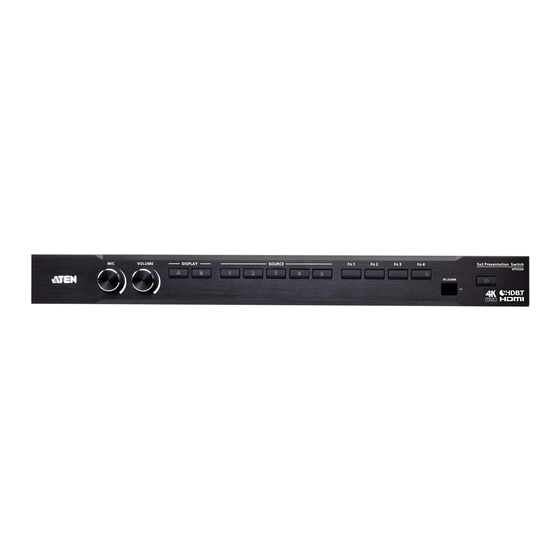
Chapter 2 Hardware Setup 1. Please review the safety information regarding the placement of this device in Safety Instructions, page 69. 2. Do not power on the VP3520 until all the necessary hardware is connected. Hardware Overview Front View 6 7 8 Component Description mic volume control... -
Page 18: Rear View
Description cable lock screw for Universal HDMI cable lock that provides the easiest way to secure an HDMI cable to most HDMI devices. ATEN LockPro audio input port Receives a line-in audio source. mic input ports Connects to a microphone. To use the phantom power for dynamic microphone, set PHANTOM switch to ON. - Page 19 VP3520 User Manual Component Description audio output ports Connect to audio output devices. stereo line output Connects to a set of active speakers. ports Lo-Z output ports Connects to an amplifier. coaxial output port Connects to a coaxial input device. IR receiver port Connects to an IR receiver to receive IR signals from the IR remote control.
-
Page 20: Ir Remote Control
Chapter 2. Hardware Setup IR Remote Control To operate the VP3520, insert the supplied IR receiver to the IR receiver port on the back panel of the VP3520. Buttons Description on / off Used to power on the VP3520 and enable / disable the standby mode. -
Page 21: Mounting
VP3520 User Manual Mounting Rack Mount The VP3520 can be mounted on a 19” (1U) system rack. To conveniently access the front panel for local configuration and operation, mount the unit in a rack with the front panel facing outward. To rack mount the VP3520, follow the steps below. -
Page 22: Installation
Chapter 2. Hardware Setup Installation Follow the steps below the safely install sources, displays, and other equipment to the VP3520. Audio Audio Power HDBaseT HDMI HDMI HDMI HDBaseT HDMI RS-232 / IR Audio IR Ethernet RS-232 Network VE802T VE802R HDMI Relay HDMI 1. - Page 23 6. (Optional) To configure the unit’s settings via RS-232 commands, connect a hardware controller (e.g., ATEN Control Box) to the VP3520. 7. (Optional) To allow access to the web interface, connect a network switch to the VP3520 using an Ethernet cable.
-
Page 24: Relay Connection
Chapter 2. Hardware Setup Relay Connection These 2 relay channels provide connections to control the project’s screen. Each relay is normally open by default. Relay Channels NO, Isolated Relays: 24 V DC 2 A Max Normally Closed Open Connects to Project screen... -
Page 25: Setting Up Controls To A Projector Screen
VP3520 User Manual Setting Up Controls to a Projector Screen To automatically bring the projector’s screen up and down by detection of source device, follow the steps below. 1. Connect a suitable Rx device (e.g., VE802R) to the VP3520 using an Ethernet cable, to which the display (e.g., projector) is connected. - Page 26 Chapter 2. Hardware Setup 3. To automatically bring the screen up when an input source device is removed and undetected by the VP3520 for a specified active time, follow the steps below. a) Connect the screen to the unit’s relay port 2. VE802R b) Log in the web console, go to Audio &...
-
Page 27: Rs-232 Serial Connection
VP3520 User Manual RS-232 Serial Connection The bidirectional RS-232 ports on the VP3520 provide serial control of the connected HDMI display. For bidirectional RS-232 control, the transmit, receive, and ground pins must be wired on both the VP3520 and the HDMI display. -
Page 28: Ir Serial Connection
Chapter 2. Hardware Setup IR Serial Connection The IR ports on the VP3520 provide IR remote control of the connected HDMI display. IR Ports Connects to HDMI display... -
Page 29: Local Operation
Chapter 3 Local Operation Overview This chapter provides information on operating the VP3520 using the front panel and IR remote control. Note: The instructions use pushbutton to refer to the front panel and button to refer to the IR remote control. Operation Considerations ... -
Page 30: Display Mode
Chapter 3. Local Operation Display Mode The VP3520 supports the following display modes: Matrix mode ( ): When enabled, the AV sources can be configured separately, capable of showing different outputs. Mirror mode ( ): When enabled, display B uses the AV source assigned for display A and shows identical content. -
Page 31: Enabling / Disabling The Panel Lock
VP3520 User Manual Enabling / Disabling the Panel Lock To prevent accidental tampering of system settings via the front panel, you can lock the panel by pressing the function selection pushbutton 4 (Fn4) for set up an idle time for an auto lock via the web console (General > Basic > Panel Auto Lock). -
Page 32: Power Led Indication
Chapter 3. Local Operation Power LED Indication The power pushbutton is equipped with an LED that indicates the power status of the VP3520. Refer to the table below for the status and supported tasks for each LED indication. LED Indication VP3520 Status Tasks (Power Pushbutton) - Page 33 VP3520 User Manual LED Indication VP3520 Status Tasks (Power Pushbutton) Green The VP3520 is To enable the standby mode to awaken. conserve power, press the power pushbutton (VP3520 front panel) / power button (IR remote control) once. To power off the unit: (1) Press and hold the power pushbutton for 3 seconds.
-
Page 34: Customizing Remote Control To Function Keys
Chapter 3. Local Operation Customizing Remote Control to Function Keys To control a connected display device using the function selection pushbuttons, follow the steps below to set up the function keys. 1. Log in the web console, go to Audio & Video > Function Key. 2. - Page 35 VP3520 User Manual 4. The IR learn LED on the unit’s front panel flashes for 10 seconds. Aim your display’s IR remote control to the IR learn LED on the unit. Press the button you would like to learn from your display’s IR remote until the countdown finishes.
- Page 36 Chapter 3. Local Operation This page is intentionally left blank.
-
Page 37: Remote Operation
Chapter 4 Remote Operation Overview This chapter provides information on how to remotely operate and configure the VP3520 via the web console. Default Network and Login Settings The VP3520 uses the following network settings and login credentials as its default settings. ... -
Page 38: Supported Web Browsers
Chapter 4. Remote Operation Supported Web Browsers The VP3520 supports access to its web UI through the following web browsers and operating systems: Operating System Web Browser Supported Version Windows 10 x64 Edge 85.0.564.67 x64 Windows 10 x64 Firefox 88.0 x64 Windows 10 x 64 Chrome 90.0.4430.93 x64... -
Page 39: Logging In The Web Console
VP3520 User Manual Logging In the Web Console 1. In a web browser, type the IP address of the VP3520. This screen appears. 2. Type the username administrator and the password. 3. Click Log In. The main screen appears. -
Page 40: The Main Screen
The VP3520 defaults to the main screen after logging in. Refer to the illustration and table below for an overview of the web console. Element Description Click the ATEN logo to visit ATEN’s official website. Device Information Indicates the device model and name. Click this icon enable the standby mode, a power-saving mode that shuts parts of the system down to allow the user to quickly resume operation when needed. -
Page 41: General Settings
VP3520 User Manual General Settings The General page includes settings such as device name, panel lock, EDID, and login password. To access the general settings, log in the web console and the screen defaults to the page. - Page 42 Display B: This mode sends the EDID of Display B to the connected sources. ATEN Default: This mode sends ATEN-predefined EDID to the connected sources. Remix: Sends the optimum EDID of the connected displays to the connected sources.
-
Page 43: Audio & Video Settings
VP3520 User Manual Audio & Video Settings Click for a list of available options under audio and video settings. Video Control Settings Use the video control page to assign video sources and configure video settings. To access the video control page, log in the web console, and then go to Audio &... - Page 44 Chapter 4. Remote Operation Display A / Display B: Shows a preview of the currently selected source and indicates the source number at the center of the preview. Click rename the source. Mirror mode: Select this option for display B to show identical video content as display A.
- Page 45 VP3520 User Manual...
- Page 46 Chapter 4. Remote Operation Auto switching: Enables the auto switching of audio-video source on Display A or Display B. Plugged: Defines the automatic switching of audio-video source on the selected display from the auto switching above when a new source is plugged in.
-
Page 47: Audio Control Settings
VP3520 User Manual Audio Control Settings To access the audio control page, log in the web console, and then go to Audio & Video > Audio Control. -
Page 48: Audio Output
Chapter 4. Remote Operation Audio Output Overall volume: Mute, unmute, and set the volume of the connected speaker. Display A Mute, unmute, and set the volume of display A. Display B Mute, unmute, and set the volume of display B. ... - Page 49 VP3520 User Manual source (connected to the audio input ports), select Embedded Audio HDMI In 3 / HDMI In 4 / HDMI In5: Mute, unmute, and set the volume of the HDMI in 3 / HDMI in 4 / HDMI in 5 source. ...
-
Page 50: Display Control Settings
Chapter 4. Remote Operation Display Control Settings Use the display control page to control the connected display and their settings. To access the display control page, log in the web console, and then go to Audio & Video > Display Control. It is recommended to configure the VP3520’s control methods and its settings before configuring the auto display control settings. - Page 51 VP3520 User Manual Auto Display: Sets the display auto power on and off function for the connected HDMI and HDBaseT displays. Display auto power on: Enables or disables the display auto power on function. The connected display will automatically power on when the VP3520 detects an input source.
- Page 52 Chapter 4. Remote Operation If the PJ-Link 1 or PJ-Link 2 control method is selected, set the IP address, port, and password before testing the control commands. To set the IP address, port, and password for the PJ-Link 1 and 2, click and the screen below appears.
- Page 53 VP3520 User Manual click and the screen below appears. Click Save when you have entered the correct IP address, port number, and password. Click Save when you have entered the correct IP address, port number, and password. Use the drop- down menu to select a command, and click Test to test the selected command.
-
Page 54: Hdcp Settings
Chapter 4. Remote Operation HDCP Settings Use the HDCP page to view and set HDCP key setting between input and ™ output ports for digital copy protection and to ensure Seamless Switch functionality between different devices. To access the HDCP page, log in the web console, and then go to Audio &... -
Page 55: Function Key Settings
VP3520 User Manual Function Key Settings Use the function key page to enable, disable, and configure the function key. You can create up to 4 functions key with 10 commands for each function key. To access the function key page, log in the web console, and then go to Audio &... - Page 56 Chapter 4. Remote Operation Click to create command for different control methods. Use the drop-down menu to select a control method. Options are Display A (CEC) / Display B (CEC) / RS-232 Serial / RS-232 HDBT Out / IR Serial / IR HDBT Out / PJ-Link 1 / PJ-Link 2 / Relay 1 / Relay ...
- Page 57 VP3520 User Manual If the RS-232 Serial or RS-232 HDBT Out control method is selected, enter a command name, select a command type between HEX and ASCII, and key-in the command. Click Test to test the command you just created.
- Page 58 Chapter 4. Remote Operation If the IR Serial or IR HDBT Out control method is selected, enter a command name, and click Learn. Follow the procedures explained in Setting Up Controls to a Projector Screen, page 13 to create up to 10 commands for the assigned function key. Click Test to test the command you just created.
- Page 59 VP3520 User Manual If the Relay 1 or Relay 2 control method is selected, simply click Test to test the command. Apply vs. Auto Apply To automatically apply the changes you make on the Video Control page, select Auto apply at the bottom of the page.
-
Page 60: System Settings
1. Prepare the firmware file you wish to apply. a) Visit the product web page from http://www.aten.com/global/en/ b) In the Support and Download tab, download a firmware file. 2. Log in the VP3520’s web console, and then go to System > Maintenance. -
Page 61: Backing Up System Settings
VP3520 User Manual Backing Up System Settings You can back up and export the VP3520’s configurations. This backup will not include the username and password settings. 1. Log in the VP3520’s web console, and then go to System > Maintenance. 2. -
Page 62: Network Settings
Chapter 4. Remote Operation Network Settings To configure the VP3520’s network connection settings, log in the web console, and then go to System > Network. IP Settings Mode: Configure the method to which the VP3520 obtains an IP address and connects to the network. -
Page 63: Ip Installer
VP3520 User Manual IP Installer Mode: Sets the VP3520 to be viewed and configured (IP address) by the IP Installer Utility. Enable: Sets the VP3520 to be viewed and configured (IP address) by the IP Installer Utility. View Only: Sets the VP3520 to be viewed only by the IP Installer Utility. -
Page 64: Configuration Settings
Chapter 4. Remote Operation Configuration Settings To configure the VP3520’s control method and its settings, log in the web console, and then go to System > Configuration. It is recommended to configure the control method on the VP3520 before using the function keys and auto display controls. -
Page 65: Configuring Rs-232 Serial And Rs-232 Hdbt Out
VP3520 User Manual Configuring RS-232 Serial and RS-232 HDBT Out You can rename the device name, and use the drop-down menus to configure the baud rate, data bit, stop bit, and parity settings. Click to bring out more settings. -
Page 66: Configuring Ir Serial And Ir Hdbt Out
Chapter 4. Remote Operation Configuring IR Serial and IR HDBT Out You can rename the device name, and use the drop-down menus to configure the repeat times settings. Click to bring out more settings. -
Page 67: Configuring Pj-Link
VP3520 User Manual Configuring PJ-Link You can rename the device name, and use the drop-down menus to select a delay interval for the PJ-Link transmission in seconds. Remember to entered the correct IP address, port number, and password. Configuring Relay 1 and Relay 2 You can rename the device name, set a pulse time in seconds, and test the configuration. - Page 68 Chapter 4. Remote Operation This Page Intentionally Left Blank...
-
Page 69: Cli Commands
Chapter 5 CLI Commands Overview The VP3520 can be configured and controlled via RS-232 or Telnet commands when connected to a host computer or other device, such as a control system. This chapter provides information on how to connect to the VP3520 via RS- 232 / Telnet and command syntax. -
Page 70: Connecting To The Vp3520 Via Rs-232
Chapter 5. CLI Commands Connecting to the VP3520 via RS-232 1. Connect a host computer or control system to the RS-232 serial port on the VP3520 unit. 2. Download and install controller software that supports RS-232 serial control and the operation system of your controller PC. 3. -
Page 71: Command Syntax
VP3520 User Manual Command Syntax The general form of a command is: command parameter<argument> {one|two|three} Notation Description The name of the command is shown in bold. command Indicates the name of the parameter. parameter Indicates the name of the value or the information that the user <argument>... -
Page 72: Command List
Chapter 5. CLI Commands Command List Use the following commands to control and configure the VP3520 via Telnet or RS-232. For details on establishing a Telnet or RS-232 session to the VP3520, see Connecting to the VP3520 via Telnet, page 57 and Connecting to the VP3520 via RS-232, page 58. -
Page 73: Setting The Display Mode
VP3520 User Manual Setting the Display Mode Function Sets the VP3520 to matrix or mirror mode. Syntax displaymode {matrix|mirror} Parameters matrix: When enabled, the AV sources can be configured separately, capable of showing different outputs. mirror: When enabled, display B uses the AV source assigned for display A and shows identical content. -
Page 74: Setting The Edid Mode
remix: Set the VP3520’s EDID mode to remix with which the system sends the optimum EDID of the connected displays to the sources. default: Set the VP3520’s EDID mode to ATEN Default which sends ATEN-predefined EDID to the connected sources (default). Example... -
Page 75: Configuring The Read Status
VP3520 User Manual off: Unmute the specified input / output ports. Example mute o01 off Configuring the Read Status Functions and Syntax Syntax Function Displays the video and audio input assigned to each read output port, EDID mode, device information, and network settings. -
Page 76: Resetting The Unit
Chapter 5. CLI Commands Resetting the Unit Function Resets the VP3520 to its default settings. Syntax reset Configuring the Scaling Functions and Syntax Syntax Function Reads the scaler settings on scaling output A and B. Configures the scaling setting for scaling o<output_port|o*>... -
Page 77: Enabling Or Disabling The Standby Mode
VP3520 User Manual Enabling or Disabling the Standby Mode Functions and Syntax Syntax Function Displays the current standby mode setting. Standby standby mode is a power-saving mode that shuts parts of the system down to allow the user to quickly resume operation when needed. -
Page 78: Configuring The Switching Mode
Chapter 5. CLI Commands Configuring the Switching Mode Function Enables or disables auto switching. Syntax swmode {auto|off} Parameters auto: Enables the auto switch (default). off: Disables the auto switch. Example swmode auto Configuring the Volume ... -
Page 79: Setting The Fan Speed
VP3520 User Manual Setting the Fan Speed Function Sets the internal fan speed that cools the VP3520. Syntax fan {low|mid|high} Parameters low: Sets the internal fan to low speed (default). mid: Sets the internal fan to normal speed. ... -
Page 80: Configuring The Audio Mapping
Chapter 5. CLI Commands Configuring the Audio Mapping Functions and Syntax Syntax Function Specifies the output port. o {output_port} Specifies an audio source from display A or src {port} display B. Sets the audio of the specified output port type {sd} (analog) to follow a specified audio source (digital) between display A or display B. -
Page 81: Appendix
Appendix Safety Instructions General This product is for indoor use only. Read all of these instructions. Save them for future reference. Follow all warnings and instructions marked on the device. Do not place the device on any unstable surface (cart, stand, table, etc.). If the device falls, serious damage will result. - Page 82 Appendix Do not attempt to service the device yourself. Refer all servicing to qualified service personnel. If the following conditions occur, unplug the device from the wall outlet and bring it to qualified service personnel for repair. The power cord or plug has become damaged or frayed. ...
-
Page 83: Rack Mounting
VP3520 User Manual Rack Mounting Before working on the rack, make sure that the stabilizers are secured to the rack, extended to the floor, and that the full weight of the rack rests on the floor. Install front and side stabilizers on a single rack or front stabilizers for joined multiple racks before working on the rack. -
Page 84: Technical Support
For telephone support, call this number: International 886-2-8692-6959 China 86-400-810-0-810 Japan 81-3-5615-5811 Korea 82-2-467-6789 North America 1-888-999-ATEN ext 4988 1-949-428-1111 North America Email Support support@aten-usa.com Online Technical Troubleshooting http://www.aten-usa.com/support Support Documentation Software Updates Telephone Support... -
Page 85: Specifications
HDBaseT: 4K@30Hz (4:4:4) up to 35 m (Cat 5e / 6) 4K@30Hz (4:4:4) up to 40 m (Cat 6a or ATEN 2L-2910 Cat 6) 1080p @60Hz up to 60 m (Cat 5e / 6) 1080p @60Hz up to 70 m (Cat 6a or ATEN 2L-2910 Cat 6) - Page 86 Selection Mic: 1 x knob Volume: 1 x knob Mode / Unlock: 1 x pushbutton Function Key: 4 x pushbuttons EDID Settings EDID Mode: ATEN Default / Display A / Remix Connectors Power 1 x 3-prong AC socket Power AC110V:48.2W:449BTU Consumption Note: If PoH (max.
- Page 87 VP3520 User Manual Environmental Operating 0 - 40°C Temperature Storage -20 - 60°C Temperature Humidity 0 x 80% RH, Non-Condensing Physical Properties Housing Metal Weight 3.80 kg (8.37 lb) Dimensions 43.24 x 27.23 x 4.40 cm (17.02 x 10.72 x 1.73 in) (L x W x H) Input Resolutions Video DCC...
- Page 88 Appendix 1920 x 1200 @ 60 Hz (reduced blanking) 1080p @ 60 Hz 480p @ 60 Hz (4:3) 480p @ 60 Hz (16:9) 720p @ 60 Hz 1080i @ 60 Hz 640 x 480 @ 60 Hz (4:3) 576p @ 50 Hz (4:3) 576p @ 50 Hz (16:9) 720p @ 50 Hz 1080i @ 50 Hz...
-
Page 89: Limited Warranty
© Copyright 2021 ATEN® International Co., Ltd. Released: 2021-10-07 ATEN and the ATEN logo are registered trademarks of ATEN International Co., Ltd. All rights reserved. All other brand names and trademarks are the registered property of their respective owners.
Need help?
Do you have a question about the VanCryst VP3520 and is the answer not in the manual?
Questions and answers