Table of Contents
Advertisement
Quick Links
Advertisement
Table of Contents

Related Manuals for Supermicro SuperServer 2049P-TN8R


Summary of Contents for Supermicro SuperServer 2049P-TN8R
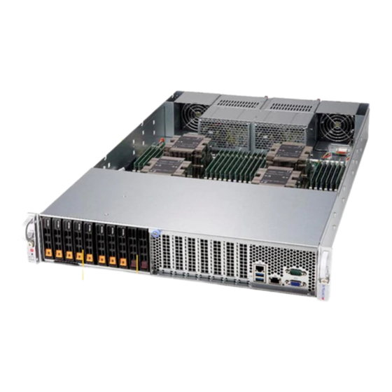
- Page 1 SuperServer ® 2049P-TN8R USER’S MANUAL Revision 1.0...
- Page 2 State of California, USA. The State of California, County of Santa Clara shall be the exclusive venue for the resolution of any such disputes. Supermicro's total liability for all claims will not exceed the price paid for the hardware product.
- Page 3 About this Manual This manual is written for professional system integrators and PC technicians. It provides information for the installation and use of the SuperServer 2049P-TN8R. Installation and maintenance should be performed by experienced technicians only. Please refer to the 2049P-TN8R server specifications page on our website for updates on supported memory, processors and operating systems (http://www.supermicro.com).
-
Page 4: Table Of Contents
SuperServer 2049P-TN8R User's Manual Contents Chapter 1 Introduction 1.1 Overview ..........................9 1.2 Unpacking the System ......................9 1.3 System Features ........................10 1.4 Server Chassis Features ....................11 Control Panel ........................11 Front Features ........................12 Rear Features ........................13 1.5 Motherboard Layout ......................14 Quick Reference Table ......................15 Chapter 2 Server Installation 2.1 Overview ..........................17... - Page 5 Preface Chapter 3 Maintenance and Component Installation 3.1 Removing Power ........................26 3.2 Accessing the System ......................26 3.3 Processor and Heatsink Installation ...................30 The Intel® Xeon® Scalable Processors Series ..............30 Overview of the Processor Carrier Assembly ..............31 Overview of the CPU Socket ....................31 Overview of the Processor Heatsink Module ..............32 Creating the Non-F Model Processor Carrier Assembly...........33 Assembling the Processor Heatsink Module ..............34...
- Page 6 SuperServer 2049P-TN8R User's Manual PCI-E Expansion Cards Installation ..................50 Installing an Expansion Card ..................50 3.5 Chassis Components ......................51 Front Bezel ........................51 Hard Drives ........................51 Drive Carrier Indicators ....................54 Hot-Swap for NVMe Drives ...................55 Checking the Temperature of an NVMe Drive ..............55 System Cooling .........................56...
- Page 7 Preface 6.6 Security Settings ......................130 6.7 Boot Settings ........................134 6.8 Save & Exit ........................136 Appendix A BIOS Error Codes Appendix B Standardized Warning Statements for AC Systems Appendix C System Specifications Appendix D UEFI BIOS Recovery Appendix E Traditional Chinese Version of Safety Warnings Appendix F CPU-Based RAID for NVMe...
- Page 8 SuperServer 2049P-TN8R User's Manual Contacting Supermicro Headquarters Address: Super Micro Computer, Inc. 980 Rock Ave. San Jose, CA 95131 U.S.A. Tel: +1 (408) 503-8000 Fax: +1 (408) 503-8008 Email: marketing@supermicro.com (General Information) support@supermicro.com (Technical Support) Website: www.supermicro.com Europe Address: Super Micro Computer B.V.
-
Page 9: Chapter 1 Introduction
2U 2200W power supply with PMBus and 200-240Vdc input, RoHS PWS-2K21A-2R1 1.2 Unpacking the System Inspect the box the SuperServer 2049P-TN8R was shipped in and note if it was damaged in any way. If any equipment appears damaged, please file a damage claim with the carrier who delivered it. -
Page 10: System Features
SuperServer 2049P-TN8R User's Manual 1.3 System Features The following table provides you with an overview of the main features of the 2049P-TN8R. Please refer to Appendix C for additional specifications. System Features Motherboard X11QPL Chassis CSE-218LTS-R2K21P Four Intel® Xeon® Scalable Processors in Socket P0 with up to 205W TDP for VM optimized SKUs. Three UltraPath Interconnects (UPI) up to 10.4GT/s per processor. -
Page 11: Server Chassis Features
Chapter 1: Introduction 1.4 Server Chassis Features Control Panel The switches and LEDs located on the control panel are described below. See Chapter 4 for details on the control panel connections. Figure 1-1. Control Panel View Control Panel Features Item Feature Description The main power button is used to apply or remove power from the power... -
Page 12: Front Features
SuperServer 2049P-TN8R User's Manual Information LED Status Description An overheat condition has occurred. Continuously on and red (This may be caused by cable congestion.) Blinking red (1Hz) Fan failure, check for an inoperative fan. Local UID has been activated. Use this function to Solid blue locate the server in a rackmount environment. -
Page 13: Rear Features
Chapter 1: Introduction Rear Features The illustration below shows the features included on the rear of the chassis. Figure 1-3. Chassis Rear View Rear Chassis Features Item Feature Description Power Supplies Two redundant power supplies Cooling Fans Two hot-swappable heavy duty cooling fans... -
Page 14: Motherboard Layout
SuperServer 2049P-TN8R User's Manual 1.5 Motherboard Layout Below is a layout of the X11QPL with jumper, connector and LED locations shown. See the table on the following page for descriptions. For detailed descriptions, pinout information and jumper settings, refer to Chapter 4. -
Page 15: Quick Reference Table
Chapter 1: Introduction Quick Reference Table Jumper Description Default Setting PWR Fail Trigger Thermal Throttle Pins 1-2 (Disabled) JBR1 Top (BOOT) Block Swap Pins 1-2 (Disabled) JBJ2 ASD Debug Enabled jumper Pins 1-2 (Disabled) JBT1 CMOS Clear Open (Normal) CPLD flash header JPB1 BMC Enabled/Disabled Pins 1-2 (Enabled) - Page 16 SuperServer 2049P-TN8R User's Manual Description Status BMC_HB_LED1 BMC Heartbeat LED Blinking Green: BMC Normal LED1 Power LED Solid Green: Power On LED2 UID LED Solid Blue: Unit Identified PCIE X8 PCIE X16 CPU2 PE1 x8 [7:0] JVS1A JVS1B Dedicated VGA CONN...
-
Page 17: Chapter 2 Server Installation
Chapter 2: Server Installation Chapter 2 Server Installation 2.1 Overview This chapter provides advice and instructions for mounting your system in a server rack. If your system is not already fully integrated with processors, system memory etc., refer to Chapter 3 for details on installing those specific components. Caution: Electrostatic Discharge (ESD) can damage electronic components. -
Page 18: Server Precautions
SuperServer 2049P-TN8R User's Manual • Always make sure the rack is stable before extending a server or other component from the rack. • You should extend only one server or component at a time - extending two or more simul- taneously may cause the rack to become unstable. -
Page 19: Circuit Overloading
Chapter 2: Server Installation Circuit Overloading Consideration should be given to the connection of the equipment to the power supply circuitry and the effect that any possible overloading of circuits might have on overcurrent protection and power supply wiring. Appropriate consideration of equipment nameplate ratings should be used when addressing this concern. -
Page 20: Installing The Rails
SuperServer 2049P-TN8R User's Manual 2.3 Installing the Rails There are a variety of rack units on the market, which may require a slightly different assembly procedure. The following is a basic guideline for installing the system into a rack with the rack mounting hardware provided. -
Page 21: Releasing The Inner Rail
Chapter 2: Server Installation Releasing the Inner Rail Each inner rail has a locking latch. This latch prevents the server from coming completely out of the rack when the chassis is pulled out for servicing. To mount the rail onto the chassis, first release the inner rail from the outer rails. Releasing Inner Rail from the Outer Rails 1. -
Page 22: Installing The Inner Rails On The Chassis
SuperServer 2049P-TN8R User's Manual Installing the Inner Rails on the Chassis Installing the Inner Rails 1. Identify the left and right inner rails. They are labeled. 2. Place the inner rail firmly against the side of the chassis, aligning the hooks on the side of the chassis with the holes in the inner rail. -
Page 23: Installing The Outer Rails Onto The Rack
Chapter 2: Server Installation Installing the Outer Rails onto the Rack Installing the Outer Rails 1. Press upward on the locking tab at the rear end of the middle rail. 2. Push the middle rail back into the outer rail. 3. -
Page 24: Sliding The Chassis Onto The Rack Rails
SuperServer 2049P-TN8R User's Manual Sliding the Chassis onto the Rack Rails Warning: Mounting the system into the rack requires at least two people to support the chassis during installation. Please follow safety recommendations printed on the rails. Installing the Chassis into a Rack 1. -
Page 25: Removing The Chassis From The Rack
Chapter 2: Server Installation Removing the Chassis from the Rack Caution! It is dangerous for a single person to off-load the heavy chassis from the rack without assistance. Be sure to have sufficient assistance supporting the chassis when removing it from the rack. -
Page 26: Chapter 3 Maintenance And Component Installation
SuperServer 2049P-TN8R User's Manual Chapter 3 Maintenance and Component Installation This chapter provides instructions on installing and replacing main system components. To prevent compatibility issues, only use components that match the specifications and/or part numbers given. Installation or replacement of most components require that power first be removed from the system. - Page 27 Chapter 3: Maintenance and Component Installation Warning: Except for short periods of time, do not operate the server without the covers in place. The chassis covers must be in place to allow for proper airflow and to prevent overheating. Figure 3-1. Removing the Chassis Front Cover...
- Page 28 SuperServer 2049P-TN8R User's Manual Figure 3-2. Removing the Chassis Back Cover...
- Page 29 Chapter 3: Maintenance and Component Installation Replacing the Top Covers 1. Align the back cover with the notches on the chassis. Slide the cover towards the front of the chassis until the cover is hooked into the notches on the chassis. 2.
-
Page 30: Processor And Heatsink Installation
Thermal grease is pre-applied on a new heatsink. No additional thermal grease is needed. • Refer to the Supermicro website for updates on processor support. • All graphics in this manual are for illustrations only. Your components may look different. -
Page 31: Overview Of The Processor Carrier Assembly
Chapter 3: Maintenance and Component Installation Overview of the Processor Carrier Assembly The processor carrier assembly contains the Intel Xeon Non-Fabric (Non-F) processor and a processor carrier. 1. Non-F Processor 2. Processor Carrier Overview of the CPU Socket The CPU socket is protected by a plastic protective cover. 1. -
Page 32: Overview Of The Processor Heatsink Module
SuperServer 2049P-TN8R User's Manual Overview of the Processor Heatsink Module The Processor Heatsink Module (PHM) contains a heatsink, a processor carrier, and the Intel Xeon Non-Fabric (Non-F) processor. 1. Heatsink with Thermal Grease 2. Processor Carrier 3. Non-F Processor Processor Heatsink Module... -
Page 33: Creating The Non-F Model Processor Carrier Assembly
Chapter 3: Maintenance and Component Installation Creating the Non-F Model Processor Carrier Assembly To install a Non-F model processor into the processor carrier, follow the steps below: 1. Hold the processor with the LGA lands (gold contacts) facing up. Locate the small, gold triangle in the corner of the processor and the corresponding hollowed triangle on the processor carrier. -
Page 34: Assembling The Processor Heatsink Module
SuperServer 2049P-TN8R User's Manual Assembling the Processor Heatsink Module After creating the processor carrier assembly for the Non-F model processor, mount it onto the heatsink to create the processor heatsink module (PHM): 1. Note the label on top of the heatsink, which marks the heatsink mounting holes as 1, 2, 3, and 4. -
Page 35: Preparing The Cpu Socket For Installation
Chapter 3: Maintenance and Component Installation Preparing the CPU Socket for Installation This motherboard comes with a plastic protective cover installed on the CPU socket. Remove it from the socket to install the Processor Heatsink Module (PHM). Gently pull up one corner of the plastic protective cover to remove it. -
Page 36: Installing The Processor Heatsink Module
SuperServer 2049P-TN8R User's Manual Installing the Processor Heatsink Module After assembling the Processor Heatsink Module (PHM), install the PHM onto the CPU socket: 1. Align hole 1 of the heatsink with the printed triangle on the CPU socket. See the left image below. -
Page 37: Removing The Processor Heatsink Module
Chapter 3: Maintenance and Component Installation Removing the Processor Heatsink Module Before removing the processor heatsink module (PHM) from the motherboard, unplug the AC power cord from all power supplies after shutting down the system. Then follow the steps below: 1. -
Page 38: Memory Support And Installation
SuperServer 2049P-TN8R User's Manual 3.4 Memory Support and Installation Note: Check the Supermicro website for recommended memory modules. Important: Exercise extreme care when installing or removing DIMM modules to prevent any damage. ESD Precautions Electrostatic Discharge (ESD) can damage electronic com ponents including memory modules. -
Page 39: Ddr4 Memory Support For The Intel Xeon Scalable-Sp Processors
Chapter 3: Maintenance and Component Installation DDR4 Memory Support for the Intel Xeon Scalable-SP Processors DDR4 Memory Support Speed (MT/s); Voltage (V); Slots Per Channel (SPC) and DIMMs Per Channel (DPC) DIMM Capacity (GB) Ranks Per 1 Slot Per Channel 2 Slots Per Channel Type DIMM &... -
Page 40: General Memory Population Requirements
SuperServer 2049P-TN8R User's Manual General Memory Population Requirements 1. Be sure to use the memory modules of the same type and speed on the motherboard. Mixing of memory modules of different types and speeds is not allowed. 2. Using unbalanced memory topology such as populating two DIMMs in one channel while populating one DIMM in another channel on the same motherboard will result in reduced memory performance. - Page 41 Chapter 3: Maintenance and Component Installation (DDR4 Only) Socket Level Population Requirements DDR4 Socket Level Minimum Population Requirements • There should be at least one DDR4 DIMM per socket. • If only one DIMM is populated in a channel, then populate it in the slot furthest away from CPU. •...
- Page 42 SuperServer 2049P-TN8R User's Manual (DDR4 Only) 2SPC Memory Configuration with x8 DIMMs Total # of DDR Channel Number Virtual DIMMs of Ranks Lock Step DIMM Population 1 x8 DIMM Must be installed on IMC0 DDR Channel 0 within an IMC >1...
- Page 43 Chapter 3: Maintenance and Component Installation (DDR4 Only) 2SPC Memory Configuration with x8/x4 DIMMs Mixed DDR4 RDIMM Total # of DIMMs DDR Channel ADDC/SDDC Features DIMM Popula- 1 pair of x8, x4 DDR0: Populate with 1 DIMM tion within an DDR1: Populate the second DIMM (for best perfor- mance) 2 pairs of x8, x4...
-
Page 44: Ddr4 Memory Population Table For The Motherboards Based-On The Intel Xeon Scalable-Sp-Based Processors
SuperServer 2049P-TN8R User's Manual DDR4 Memory Population Table for the Motherboards based-on the Intel Xeon Scalable-SP-based Processors Note: Unbalanced memory configuration decreases memory performance and is not recommended for Supermicro motherboards. DDR4 Memory Population Table w/Half Memory Configuration Support (w/24 DIMMs Installed) Memory Population Table for the 4-way Motherboard w/Half Memory Configuration Support (X11QPL w/4 CPUs &... -
Page 45: Dcpmm Population For The Motherboards Based On The 2Nd Gen Intel Xeon Scalable-Sp Processors With Full Configuration (48-Dimms Installed)
Scalable-SP Processors with Full Configuration (48-DIMMs Installed) Notes: 1. Unbalanced memory configuration decreases memory performance and is not recommended for Supermicro motherboards. 2. DCPMM memory is supported by the 2nd Gen Intel Xeon Scablable-SP (82xx/62xx/52xx series) processors only. Symmetric Population... - Page 46 SuperServer 2049P-TN8R User's Manual Symmetric Population 2-2-1 (For Channel Configuration: 2-2-1) Modes P1-DIMMF1 P1-DIMMF2 P1-DIMME1 P1-DIMME2 P1-DIMMD1 P1-DIMMD2 P1-DIMMA2 P1-DIMMA1 P1-DIMMB2 P1-DIMMB1 P1-DIMMC2 P1-DIMMC1 CPU1 DRAM1 DRAM1 DCPMM DRAM1 DCPMM DCPMM DRAM1 DCPMM DRAM1 DRAM1 DRAM1 DRAM1 DRAM1 DRAM1 DRAM1...
- Page 47 Chapter 3: Maintenance and Component Installation Asymmetric Population 2/1- (For Channel Configuration: 2/1-1-1) Modes P1-DIMMF1 P1-DIMMF2 P1-DIMME1 P1-DIMME2 P1-DIMMD1 P1-DIMMD2 P1-DIMMA2 P1-DIMMA1 P1-DIMMB2 P1-DIMMB1 P1-DIMMC2 P1-DIMMC1 CPU1 DRAM1 DRAM1 DRAM1 DCPMM DRAM1 DRAM1 DRAM1 CPU2 P2-DIMMF1 P2-DIMMF2 P2-DIMME1 P2-DIMME2 P2-DIMMD1 P2-DIMMD2 P2-DIMMA2 P2-DIMMA1...
-
Page 48: Dimm Installation
SuperServer 2049P-TN8R User's Manual LED2 LAN1 IPMI_LAN USB3.0 JBJ2 JPME1 DIMM Installation SRW3 SRW4 JPCIE1 JPCIE3 JPCIE4 JPCIE5 JPCIE6 JPCIE7 JPCIE2 JPB1 JBR1 SRW1 SRW2 JPG1 1. Follow the instructions given in the JTPM1 JUSB1 JPME2 JUSB2 JWD1 memory population guidelines listed in... -
Page 49: Motherboard Battery
Chapter 3: Maintenance and Component Installation Motherboard Battery The motherboard uses non-volatile memory to retain system information when system power is removed. This memory is powered by a lithium battery residing on the motherboard. Replacing the Battery Begin by removing power from the system as described in section 3.1. 1. -
Page 50: Pci-E Expansion Cards Installation
SuperServer 2049P-TN8R User's Manual PCI-E Expansion Cards Installation The system supports seven low-profile PCI-E 3.0 expansion slots at the front of the chassis. Two expansion slots are x16 slots and five are x8 slots. Installing an Expansion Card 1. Turn off the system and remove the power cords as described in Section 3.1. -
Page 51: Chassis Components
Chapter 3: Maintenance and Component Installation 3.5 Chassis Components Front Bezel If your system has an optional bezel attached to the front of the chassis, you will need to remove it to gain access to the drive bays. 1. Unlock the front of the chassis and then press the release knob. 2. - Page 52 SuperServer 2049P-TN8R User's Manual SCALE 2:5 Figure 3-6. Removing a Drive Carrier...
- Page 53 Caution: Except for short periods of time while swapping hard drives, do not operate the server without the carriers in the drive bays. Note: Enterprise level hard disk drives are recommended for use in Supermicro chassis and servers. For information on recommended HDDs, visit the Supermicro website at http://www.
-
Page 54: Drive Carrier Indicators
Blinking at 1 Hz Attention state—do not remove NVMe device (not supported in VMD mode) Note: Enterprise level hard disk drives are recommended for use in Supermicro chassis and servers. For information on recommended HDDs, visit the Supermicro website at https://www. -
Page 55: Hot-Swap For Nvme Drives
Chapter 3: Maintenance and Component Installation Hot-Swap for NVMe Drives An NVMe drive can be inserted and replaced using IPMI. Note: If you are using VROC, see the VROC appendix in this manual instead. Ejecting a Drive 1. IPMI > Server Health > NVMe SSD 2. -
Page 56: System Cooling
2. Grab the grips at the top and bottom of the fan and pull the fan out of the chassis. 3. Replace the failed fan with an identical fan, available from Supermicro. Push the new fan into the housing, making sure the air flow direction is the same. -
Page 57: Air Shroud
Chapter 3: Maintenance and Component Installation Air Shroud Cooling is also improved by installing the standard air shroud. 1. If necessary, remove power as described in Section 3.1 and remove the top covers as described in Section 3.2. 2. Place the airshroud over the CPUs. 3. -
Page 58: Power Supply
SuperServer 2049P-TN8R User's Manual Power Supply The 2049P-TN8R has a 2200 Watt redundant power supply consisting of two power modules. They have an auto-switching capability, which enables them to automatically sense and operate at a 100V-240V input voltage. If either of the two power supply modules fail, the other module will take the full load and allow the system to continue operation without interruption. - Page 59 Chapter 3: Maintenance and Component Installation Replacing the Power Supply 1. Turn off the system and unplug the power cord from the power source. Unplug the power cord from the power supply module. Warning: The power supply modules are NOT hot-swappable. 2.
-
Page 60: Chapter 4 Motherboard Connections
SuperServer 2049P-TN8R User's Manual Chapter 4 Motherboard Connections This section describes the connections on the motherboard and provides pinout definitions. Note that depending on how the system is configured, not all connections are required. The LEDs on the motherboard are also described here. A motherboard layout indicating component locations may be found in Chapter 1. -
Page 61: Headers And Connectors
Chapter 4: Motherboard Connections 4.2 Headers and Connectors Onboard Fan Header This motherboard has six fan headers (FAN1~FAN6) used for CPU/system cooling. These are all 6-pin fan headers, which are backward compatible with a traditional 4-pin fan. The onboard fan speed is controlled by Thermal Management (via Hardware Monitoring) in the BIOS. - Page 62 SuperServer 2049P-TN8R User's Manual I-SATA 3.0 Ports The X11QPL has four I-SATA 3.0 ports (I-SATA0-3). These ports, supported by the Intel C621 chipset, provide serial-link signal connections. SATA 3.0 Port Pin Definitions Pin# Signal Ground SATA_TXP SATA_TXN Ground SATA_RXN SATA_RXP Ground M.2 Connection...
-
Page 63: Ports
Chapter 4: Motherboard Connections 4.3 Ports Front I/O Ports See Figure 4-1 below for the locations and descriptions of the various I/O ports on the front of the motherboard. LED2 IPMI_LAN LAN1 USB3.0 JBJ2 JPME1 SRW3 SRW4 JPCIE4 JPCIE1 JPCIE3 JPCIE5 JPCIE6 JPCIE7... - Page 64 UID Indicator provides easy identification of a system unit that may be in need of service. Note: UID can also be triggered via IPMI on the motherboard. For more information on IPMI, please refer to the IPMI User's Guide posted on our website at http://www.supermicro.com. UID Switch...
- Page 65 Chapter 4: Motherboard Connections Universal Serial Bus (USB) Ports There are two USB 3.0 ports (USB2/3) on the I/O front panel. A USB header that supports two USB 3.0 connections (USB0/1) is located on the motherboard to provide front access support.
-
Page 66: Front Control Panel
JF1 contains header pins for various buttons and indicators that are normally located on a control panel at the front of the chassis. These connectors are designed specifically for use with Supermicro chassis. See the figure below for the descriptions of the front control panel buttons and LED indicators. - Page 67 Chapter 4: Motherboard Connections Power Button The Power Button connection is located on pins 1 and 2 of JF1. Momentarily contacting both pins will power on/off the system. This button can also be configured to function as a suspend button (with a setting in the BIOS - see Chapter 4). To turn off the power when the system is in suspend mode, press the button for 4 seconds or longer.
- Page 68 SuperServer 2049P-TN8R User's Manual OH/Fan Fail/PWR Fail/UID LED Connect an LED cable to pins 7 and 8 of the Front Control Panel (JF1) to use UID/Overheat/ Fan Fail/Power Fail LED connections. The LED on pin 8 provides warnings of overheat, power failure or fan failure.
- Page 69 Chapter 4: Motherboard Connections NIC1/NIC2 (LAN1/LAN2) The NIC (Network Interface Controller) LED connection for LAN port 1 is located on pins 11 and 12 of JF1, and LAN port 2 is on pins 9 and 10. Attach the NIC LED cables here to display network activity.
-
Page 70: Jumpers
SuperServer 2049P-TN8R User's Manual 4.4 Jumpers Explanation of Jumpers To modify the operation of the motherboard, jumpers are used to choose between optional settings. Jumpers create shorts between two pins to change the function associated with it. Pin 1 is identified with a square solder pad on the printed circuit board. See the motherboard layout page for jumper locations. - Page 71 Chapter 4: Motherboard Connections Power-Failure Throttling Enable/Disable The Power-Failure Throttling jumper is located at J1. Close pins 2-3 of J1 to enable power throttling feature. The default setting is to close pins 1-2 for normal (Disabled) operation. See the jumper setting table below. Power-Failure Throttling Jumper Settings Jumper Setting...
- Page 72 SuperServer 2049P-TN8R User's Manual VGA Enable/Disable JPG1 allows you to enable or disable the VGA port, which is supported by the onboard BMC controller. The default setting is Enabled. VGA Enable/Disable Jumper Settings Jumper Setting Definition Pins 1-2 Enabled Pins 2-3...
-
Page 73: Led Indicators
Chapter 4: Motherboard Connections 4.5 LED Indicators IPMI LAN LEDs A dedicated IPMI LAN, supported by the onboard Baseboard Management controller, is located on the I/O front panel. The amber LED on the right indicates activity, while the green LED on the left indicates the speed of the connection. -
Page 74: Chapter 5 Software
USB/SATA DVD drive, or a USB flash drive, or the IPMI KVM console. 2. Retrieve the proper RST/RSTe driver. Go to the Supermicro web page for your motherboard and click on "Download the Latest Drivers and Utilities", select the proper driver, and copy it to a USB flash drive. - Page 75 Chapter 5: Software 4. During Windows Setup, continue to the dialog where you select the drives on which to install Windows. If the disk you want to use is not listed, click on “Load driver” link at the bottom left corner. Figure 5-2.
-
Page 76: Driver Installation
The Supermicro website contains drivers and utilities for your system at https://www. supermicro.com/wftp/driver. Some of these must be installed, such as the chipset driver. After accessing the website, go into the CDR_Images (in the parent directory of the above link) and locate the ISO file for your motherboard. Download this file to a USB flash drive or a DVD. -
Page 77: Superdoctor ® 5
5.3 SuperDoctor ® The Supermicro SuperDoctor 5 is a program that functions in a command-line or web-based interface for Windows and Linux operating systems. The program monitors such system health information as CPU temperature, system voltages, system power consumption, fan speed, and provides alerts via email or Simple Network Management Protocol (SNMP). -
Page 78: Chapter 6 Uefi Bios
SuperServer 2049P-TN8R User's Manual Chapter 6 UEFI BIOS 6.1 Introduction This chapter describes the AMIBIOS™ setup utility for the X11QPL motherboard. The BIOS is stored on a chip and can be easily upgraded using a flash program. Note: Due to periodic changes to the BIOS, some settings may have been added or deleted and might not yet be recorded in this manual. -
Page 79: Main Setup
Note: The time is in the 24-hour format. For example, 5:30 P.M. appears as 17:30:00. The date's default value is the BIOS build date after the RTC (Real Time Clock) reset. Supermicro X11QPL BIOS Version This feature displays the version of the BIOS ROM used in the system. - Page 80 SuperServer 2049P-TN8R User's Manual Memory Information Total Memory This feature displays the total size of memory available in the system. Memory Speed This feature displays the default speed of the memory modules installed in the system.
-
Page 81: Advanced Setup Configurations
Chapter 6: UEFI BIOS 6.3 Advanced Setup Configurations Use the arrow keys to select the Advanced submenu and press <Enter> to access the submenu items: Warning: Take Caution when changing the Advanced settings. An incorrect value, an improper DRAM frequency, or a wrong BIOS timing setting may cause the system to malfunction. When this occurs, restore the setting to the manufacturer default setting. - Page 82 SuperServer 2049P-TN8R User's Manual Wait For 'F1' If Error Select Enabled to force the system to wait until the <F1> key is pressed if an error occurs. The options are Disabled and Enabled. Interrupt 19 Capture Interrupt 19 is the software interrupt that handles the boot disk function. When this feature is set to Immediate, the ROM BIOS of the host adaptors will "capture"...
- Page 83 Chapter 6: UEFI BIOS CPU Configuration Warning: Setting the wrong values in the following sections may cause the system to malfunc- tion. Processor Configuration The following CPU information will display: • Processor BSP Revision • Processor Socket • Processor ID •...
- Page 84 SuperServer 2049P-TN8R User's Manual prevent a worm or a virus from flooding illegal codes to overwhelm the processor, causing damages to the system during a virus attack. The options are Enable and Disable. (Refer to Intel and Microsoft websites for more information.)
- Page 85 Chapter 6: UEFI BIOS Extended APIC (Extended Advanced Programmable Interrupt Controller) Based on the Intel Hyper-Threading technology, each logical processor (thread) is assigned 256 APIC IDs (APIDs) in 8-bit bandwidth. When this feature is set to Enable, the APIC ID will be expanded from 8 bits to 16 bits to provide 512 APIDs to each thread to enhance CPU performance.
- Page 86 SuperServer 2049P-TN8R User's Manual Config (Configure) TDP (Available when SpeedStep is set to Enable) Use this feature to set the appropriate TDP (Thermal Design Power) level for the system. The TDP refers to the maximum amount of power allowed for running "real applications"...
- Page 87 Chapter 6: UEFI BIOS CPU C6 Report (Available when Autonomous Core C-State is set to Disable) Select Enable to allow the BIOS to report the CPU C6 state (ACPI C3) to the operating system. During the CPU C6 state, power to all caches is turned off. The options are Auto, Enable, and Disable.
- Page 88 SuperServer 2049P-TN8R User's Manual • UPI Global MMIO Low Base/Limit • UPI Global MMIO High Base/Limit • UPI PCI-E Configuration Base/Size Degrade Precedence Use this feature to select the degrading precedence option for Ultra Path Interconnect (UPI) connections. Select Topology Precedent to degrade UPI features if system options are in conflict.
- Page 89 Chapter 6: UEFI BIOS Stale AtoS (A to S) The in-memory directory has three states: I, A, and S states. The I (-invalid) state indicates that the data is clean and does not exist in the cache of any other sockets. The A (-snoop All) state indicates that the data may exist in another socket in an exclusive or modified state.
- Page 90 SuperServer 2049P-TN8R User's Manual Memory Frequency Use this feature to set the maximum memory frequency for onboard memory modules. The options are Auto, 1866, 2000, 2133, 2400, 2666, and 2933. (Note: 2933 MHz memory is supported by the 2nd Gen Intel Xeon Scablable-SP 82xx/62xx series processors only.)
- Page 91 Chapter 6: UEFI BIOS Reset Trigger ADR (Async DIMM Self-Refresh) Upon system power loss, an ADR sequence will be triggered to allow ADR to flush the write-protected data buffers in the memory controller and place the DRAM memory in self- refresh mode.
- Page 92 SuperServer 2049P-TN8R User's Manual Static Virtual Lockstep Mode Select Enable to support Static Virtual Lockstep mode to enhance memory performance. The options are Enable and Disable. Mirror Mode Use this feature to configure the mirror mode settings for all 1LM/2LM memory modules installed in the system which will create a duplicate copy of data stored in the memory to increase memory security, but it will reduce the memory capacity into half.
- Page 93 Chapter 6: UEFI BIOS Patrol Scrub Patrol Scrubbing is a process that allows the CPU to correct correctable memory errors detected in a memory module and send the corrections to the requestor (the original source). When this feature is set to Enable, the IO hub will read and write back one cache line every 16K cycles if there is no delay caused by internal processing.
- Page 94 SuperServer 2049P-TN8R User's Manual Socket 0 PCI-E Br0D00F0 - Port 0/DMI (Available for CPU 1 Configuration) Link Speed Use this feature to configure the link speed of a PCI-E port specified by the user. The options are Auto, Gen 1 (Generation 1) (2.5 GT/s), Gen 2 (Generation 2) (5 GT/s), and...
- Page 95 Chapter 6: UEFI BIOS PCI-E Port Max (Maximum) Payload Size (Available for CPU 1 Configuration only) Select Auto for the system BIOS to automatically set the maximum payload value for a PCI-E device specified by to user for system performance enhancement. The options are Auto, 128B, and 256B.
- Page 96 SuperServer 2049P-TN8R User's Manual PassThrough DMA Select Enable for the Non-Isoch VT-d engine to pass through DMA (Direct Memory Access) to enhance system performance. The options are Enable and Disable. Select Enable to enable ATS (Address Translation Services) support for the Non-Isoch VT-d engine to enhance system performance.
- Page 97 Chapter 6: UEFI BIOS PCI-E Completion Timeout (Global) Disable Use this feature to select the PCI-E Completion Time-out settings. The options are Yes, No, and Per-Port. South Bridge The following South Bridge information will display: • USB Module Version • USB Devices Legacy USB Support Select Enabled to support onboard legacy USB devices.
- Page 98 SuperServer 2049P-TN8R User's Manual • General ME Configuration • Oper. (Operational) Firmware Version • Backup Firmware Version • Recovery Firmware Version • ME Firmware Status #1/ME Firmware Status #2 • Current State • Error Code (PCH) SATA Configuration When this submenu is selected, the AMI BIOS automatically detects the presence of the SATA...
- Page 99 Chapter 6: UEFI BIOS SATA Port 0 - SATA Port 3/M.2 SATA Port 1 Hot Plug Select Enable to support Hot-plugging for the device installed on a selected SATA port which will allow the user to replace the device installed in the slot without shutting down the system.
- Page 100 SuperServer 2049P-TN8R User's Manual sSATA RAID Option ROM/UEFI Driver (Available when Configure sSATA as is set to RAID) Select EFI to load the EFI driver for system boot. Select Legacy to load a legacy driver for system boot. The options are Disable, EFI, and Legacy.
- Page 101 Chapter 6: UEFI BIOS MMIO High Granularity Size Use this feature to select the high memory size according to memory-address mapping for the IO hub. The options are 1G, 4G, 16G, 64G, 256G, and 1024G. Maximum Read Request Select Auto for the system BIOS to automatically set the maximum size for a read request for a PCI-E device to enhance system performance.
- Page 102 SuperServer 2049P-TN8R User's Manual *If "Network Stack" is set to Enabled, the following items will display: Ipv4 PXE Support Select Enabled to enable Ipv4 PXE boot support. If this feature is disabled, it will not create the Ipv4 PXE boot option. The options are Disabled and Enabled.
- Page 103 Chapter 6: UEFI BIOS Change Settings This feature specifies the base I/O port address and the Interrupt Request address of Serial Port 1. Select Auto for the BIOS to automatically assign the base I/O and IRQ address to a serial port specified. The options for Serial Port 1 are Auto, (IO=3F8h;...
- Page 104 SuperServer 2049P-TN8R User's Manual Console Redirection Settings (for COM 1) Terminal Type Use this feature to select the target terminal emulation type for Console Redirection. Select VT100 to use the ASCII Character set. Select VT100+ to add color and function key support.
- Page 105 Chapter 6: UEFI BIOS Resolution 100x31 Select Enabled for extended-terminal resolution support. The options are Disabled and Enabled. Putty KeyPad This feature selects Function Keys and KeyPad settings for Putty, which is a terminal emulator designed for the Windows OS. The options are VT100, LINUX, XTERMR6, SCO, ESCN, and VT400.
- Page 106 SuperServer 2049P-TN8R User's Manual the parity bit is set to 0, and the number of 1's in data bits is odd. Select None if you do not want to send a parity bit with your data bits in transmission. Select Mark to add a mark as a parity bit to be sent along with the data bits.
- Page 107 Chapter 6: UEFI BIOS Redirection After BIOS Post Use this feature to enable or disable Legacy Console Redirection after BIOS POST. When the option-Bootloader is selected, Legacy Console Redirection is disabled before booting the OS. When the option-Always Enable is selected, Legacy Console Redirection remains enabled upon OS bootup.
- Page 108 SuperServer 2049P-TN8R User's Manual The setting for each these features is displayed: Data Bits, Parity, Stop Bits ACPI Settings Use this feature to configure Advanced Configuration and Power Interface (ACPI) power management settings for your system. NUMA Support (Available when the OS supports this feature) Select Enabled to enable Non-Uniform Memory Access support to enhance system perfor- mance.
- Page 109 Chapter 6: UEFI BIOS Security Device Support If this feature and the TPM jumper (JPT1) on the motherboard are both enabled, the onboard security (TPM) device will be enabled in the BIOS to enhance data integrity and system security. Please note that the OS will not show the security device. Neither TCG EFI protocol nor INT1A interaction will be made available for use.
- Page 110 SuperServer 2049P-TN8R User's Manual by the TPM or a manufacturer to be constrained to an authentic TPM device that is attached to an authentic platform. A primary key can be an encrypted, and a certificate can be created using TPM2_ ActivateCredential. It allows the user to independently enable "flag, policy, and authorization value"...
- Page 111 Chapter 6: UEFI BIOS Select this feature to keep the changes you have made and exit from the system. Discard Changes and Exit Select this feature to discard the changes you have made and exit from the system. Delete Certification ...
- Page 112 SuperServer 2049P-TN8R User's Manual Disk Memory • Disk Memory Type: This feature specifies the type of memory that is available for you to create a RAM disk. The options are Boot Service Data and Reserved. Create Raw This feature allows the user to create a raw RAM disk from all available memory modules in the system.
- Page 113 Chapter 6: UEFI BIOS Intel® Optane® DC Persistent Memory Configuration When you select this submenu and press <Enter>, the following screen will display: • Version: This feature displays the version of DCPMM used in the system. • Select an action below •...
- Page 114 SuperServer 2049P-TN8R User's Manual • DIMM Handle: This feature displays the unique handle that the CPU assigns to the DCPMM module. • DIMM Physical ID: This feature displays the physical ID of the DCPMM module. • Manageability State: This feature indicates the manageability state of the DCPMM module.
- Page 115 Chapter 6: UEFI BIOS • Subsystem Revision ID • Interface Format Code • Manufacturing Information Valid • Manufacturing Date • Manufacturing Location • Memory Type • Memory Bank Label • Data Width Label [b] • Total Width [b] • Speed [MHz] •...
- Page 116 SuperServer 2049P-TN8R User's Manual • Package Sparing Capable • Package Sparing Enabled • Package Spares Available • Configuration Status • SKU Violation • ARS Status • Overwrite DIMM Status • Last Shutdown Time • First Fast Refresh • Viral Policy Enable •...
- Page 117 Chapter 6: UEFI BIOS • Master Passphrase Enabled Monitor Health Select this submenu to view the health status and thresholds of the DCPMM module specified by the user. • Sensor Type: This feature displays the type of health items that are being monitored. •...
- Page 118 SuperServer 2049P-TN8R User's Manual • Current Firmware Version: This feature displays the current firmware version. • Selected Firmware Version: This feature allows the user to select a new firmware ver- sion to use. • File: This feature allows the user to specify the file path in the root directory that contains the new firmware for firmware update.
- Page 119 Chapter 6: UEFI BIOS Select Enabled to display the First Fast Fresh state for onboard DCPMM modules. Enable First Fast Fresh State Select Enabled to support the first fast fresh state of DCPMM data policy. Disable First Fast Fresh State Select Disable to disable the first fast fresh state of DCPMM data policy.
- Page 120 SuperServer 2049P-TN8R User's Manual Regions Current Configuration Region ID 1/Region ID 2/Region ID 3 When this submenu is selected, the following items will display: • Region ID: This feature displays the Region ID of the DCPMM module. •...
- Page 121 Chapter 6: UEFI BIOS Namespace Label Version Use this feature to view and modify the namespace label version to initialize when creating goals. The options are 1.2 and 1.1. Back to Regions Menu Select this feature and press <Enter> to go back to the Regions submenu. Back to Main Menu ...
- Page 122 SuperServer 2049P-TN8R User's Manual Delete After configuring the settings for the namespace above, click on <delete> to delete the changes you've made on the namespace. Please note that all data contained in the namespace will be deleted as well when you press <delete>.
- Page 123 Chapter 6: UEFI BIOS • App. Direct Capacity: This feature specifies the App. direct capacity of the DCPMM module. • Memory Capacity: This feature specifies the memory capacity of the DCPMM module. • Unconfigured Capacity: This feature specifies the capacity of the DCPMM module that has not been configured.
- Page 124 SuperServer 2049P-TN8R User's Manual Select Enabled for the security diagnostics test to be performed on the DCPMM module. The options are Enabled and Disabled. Execute Tests Select this feature and press <Enter> to execute the selected diagnostic tests. The following items will display: •...
-
Page 125: Event Logs
Chapter 6: UEFI BIOS 6.4 Event Logs Use this feature to configure Event Log settings. Note: After you've made a change on a setting below, please be sure to reboot the system for the change to take effect. Change SMBIOS Event Log Settings Enabling/Disabling Options SMBIOS Event Log Select Enabled to enable SMBIOS (System Management BIOS) Event Logging during system... - Page 126 SuperServer 2049P-TN8R User's Manual SMBIOS Event Log Standard Settings Log System Boot Event Select Enabled to log system boot events. The options are Enabled and Disabled. MECI (Multiple Event Count Increment) Enter the increment value for the multiple event counter. Enter a number between 1 to 255.
-
Page 127: Ipmi
Chapter 6: UEFI BIOS 6.5 IPMI Use this feature to configure Intelligent Platform Management Interface (IPMI) settings. When you select this submenu and press the <Enter> key, the following information will display: • IPMI Firmware Revision: This feature indicates the IPMI firmware revision used in your system. - Page 128 SuperServer 2049P-TN8R User's Manual When SEL is Full This feature allows the user to determine what the BIOS should do when the system event log is full. Select Erase Immediately to erase all events in the log when the system event log is full.
- Page 129 Chapter 6: UEFI BIOS IPMI LAN Selection (Available when Update IPMI LAN Configuration is set to Yes) Use this feature to select the type of the IPMI LAN. The options are Dedicated, Shared, and Failover. VLAN Select Enabled to enable IPMI VLAN function support. The default setting is Disabled. Configuration Address Source Use this feature to select the IP address source for this computer.
- Page 130 SuperServer 2049P-TN8R User's Manual 6.6 Security Settings This menu allows the user to configure the following security settings for the system. Administrator Password Use this feature to set the administrator password which is required to enter the BIOS setup utility. The length of the password should be from 3 characters to 20 characters long.
- Page 131 Chapter 6: UEFI BIOS Secure Boot When you select this submenu and press the <Enter> key, the following items will display: • System Mode Secure Boot Select Enabled to use Secure Boot settings. The options are Enabled and Disabled. Secure Boot Mode Use this feature to select the desired secure boot mode for the system.
- Page 132 SuperServer 2049P-TN8R User's Manual Export Secure Boot Variables This feature is used to copy the NVRAM content of Secure Boot variables to a storage device. Enroll EFI Image Select this feature and press <Enter> to specify an EFI (Extensible Firmware Interface) image for the system to use when it operates in the Secure Boot mode.
- Page 133 Chapter 6: UEFI BIOS of the forbidden signatures. Select Update to update your "Forbidden Signatures". Select Append to append your "Forbidden Signatures". The settings are Update, and Append. Authorized TimeStamps This feature allows the user to set and save the timestamps for the authorized signatures which will indicate the time when these signatures are entered into the system.
- Page 134 SuperServer 2049P-TN8R User's Manual 6.7 Boot Settings Use this feature to configure Boot Settings: Boot Mode Select Use this feature to select the type of devices from which the system will boot. The options are Legacy, UEFI (Unified Extensible Firmware Interface), and Dual.
- Page 135 Chapter 6: UEFI BIOS Delete Boot Option Use this feature to select a boot device to delete from the boot priority list. Delete Boot Option Use this feature to remove an EFI boot option from the boot priority list. ...
- Page 136 SuperServer 2049P-TN8R User's Manual 6.8 Save & Exit Select the Save & Exit menu from the BIOS setup screen to configure the settings below. Save Options Discard Changes and Exit Select this option to exit from the BIOS setup utility without making any permanent changes to the system configuration and reboot the computer.
- Page 137 Chapter 6: UEFI BIOS Default Options Restore Optimized Defaults To set this feature, select Restore Defaults from the Exit menu and press <Enter> to load manufacturer default settings which are intended for maximum system performance but not for maximum stability. Save As User Defaults To set this feature, select Save as User Defaults from the Exit menu and press <Enter>.
- Page 138 SuperServer 2049P-TN8R User's Manual Appendix A BIOS Error Codes A.1 BIOS Error Beep (POST) Codes During the POST (Power-On Self-Test) routines, which are performed each time the system is powered on, errors may occur. Non-fatal errors are those which, in most cases, allow the system to continue the boot-up process.
- Page 139 When BIOS performs the Power On Self Test, it writes checkpoint codes to I/O port 0080h. If the computer cannot complete the boot process, a diagnostic card can be attached to the computer to read I/O port 0080h (Supermicro p/n AOC-LPC80-20). For information on AMI updates, please refer to http://www.ami.com/products/.
- Page 140 Supermicro's Technical Support department for assistance. Only certified technicians should attempt to install or configure components. Read this appendix in its entirety before installing or configuring components in the Supermicro chassis. These warnings may also be found on our website at http://www.supermicro.com/about/...
- Page 141 Appendix B: Standardized Warning Statements Warnung WICHTIGE SICHERHEITSHINWEISE Dieses Warnsymbol bedeutet Gefahr. Sie befinden sich in einer Situation, die zu Verletzungen führen kann. Machen Sie sich vor der Arbeit mit Geräten mit den Gefahren elektrischer Schaltungen und den üblichen Verfahren zur Vorbeugung vor Unfällen vertraut. Suchen Sie mit der am Ende jeder Warnung angegebenen Anweisungsnummer nach der jeweiligen Übersetzung in den übersetzten Sicherheitshinweisen, die zusammen mit diesem Gerät ausgeliefert wurden.
- Page 142 SuperServer 2049P-TN8R User's Manual . ٌ ا ك ً ف حالة و ٌ يك أى تتسبب ف اصابة جسذ ة ٌ هذا الزهز ع ٌ خطز !تحذ ز قبل أى تعول عىل أي هعذات،يك عىل علن بالوخاطز ال ا ٌجوة عي الذوائز...
- Page 143 Appendix B: Standardized Warning Statements Warnung Vor dem Anschließen des Systems an die Stromquelle die Installationsanweisungen lesen. ¡Advertencia! Lea las instrucciones de instalación antes de conectar el sistema a la red de alimentación. Attention Avant de brancher le système sur la source d'alimentation, consulter les directives d'installation. .יש...
- Page 144 SuperServer 2049P-TN8R User's Manual Warnung Dieses Produkt ist darauf angewiesen, dass im Gebäude ein Kurzschluss- bzw. Überstromschutz installiert ist. Stellen Sie sicher, dass der Nennwert der Schutzvorrichtung nicht mehr als: 250 V, 20 A beträgt. ¡Advertencia! Este equipo utiliza el sistema de protección contra cortocircuitos (o sobrecorrientes) del edificio.
- Page 145 Appendix B: Standardized Warning Statements Power Disconnection Warning Warning! The system must be disconnected from all sources of power and the power cord removed from the power supply module(s) before accessing the chassis interior to install or remove system components. 電源切断の警告...
- Page 146 SuperServer 2049P-TN8R User's Manual يجب فصم اننظاو من جميع مصادر انطاقت وإ ز انت سهك انكهرباء من وحدة امداد انطاقت قبم انىصىل إىن امنناطق انداخهيت نههيكم نتثبيج أو إ ز انت مكىناث الجهاز 경고! 시스템에 부품들을 장착하거나 제거하기 위해서는 섀시 내부에 접근하기 전에 반드시 전원...
- Page 147 Appendix B: Standardized Warning Statements Attention Il est vivement recommandé de confier l'installation, le remplacement et la maintenance de ces équipements à des personnels qualifiés et expérimentés. !אזהרה .צוות מוסמך בלבד רשאי להתקין, להחליף את הציוד או לתת שירות עבור הציוד واملدربيه...
- Page 148 SuperServer 2049P-TN8R User's Manual Warnung Diese Einheit ist zur Installation in Bereichen mit beschränktem Zutritt vorgesehen. Der Zutritt zu derartigen Bereichen ist nur mit einem Spezialwerkzeug, Schloss und Schlüssel oder einer sonstigen Sicherheitsvorkehrung möglich. ¡Advertencia! Esta unidad ha sido diseñada para instalación en áreas de acceso restringido. Sólo puede obtenerse acceso a una de estas áreas mediante la utilización de una herramienta especial,...
- Page 149 Appendix B: Standardized Warning Statements Battery Handling Warning! There is the danger of explosion if the battery is replaced incorrectly. Replace the battery only with the same or equivalent type recommended by the manufacturer. Dispose of used batteries according to the manufacturer's instructions 電池の取り扱い...
- Page 150 SuperServer 2049P-TN8R User's Manual هناك خطر من انفجار يف حالة اسحبذال البطارية بطريقة غري صحيحة فعليل اسحبذال البطارية فقط بنفس النىع أو ما يعادلها مام أوصث به الرشمة املصنعة جخلص من البطاريات املسحعملة وفقا لحعليامت الرشمة الصانعة 경고! 배터리가 올바르게 교체되지 않으면 폭발의 위험이 있습니다. 기존 배터리와 동일하거나 제...
- Page 151 Appendix B: Standardized Warning Statements ¡Advertencia! Puede que esta unidad tenga más de una conexión para fuentes de alimentación. Para cortar por completo el suministro de energía, deben desconectarse todas las conexiones. Attention Cette unité peut avoir plus d'une connexion d'alimentation. Pour supprimer toute tension et tout courant électrique de l'unité, toutes les connexions d'alimentation doivent être débranchées.
- Page 152 SuperServer 2049P-TN8R User's Manual Backplane Voltage Warning! Hazardous voltage or energy is present on the backplane when the system is operating. Use caution when servicing. バックプレーンの電圧 システムの稼働中は危険な電圧または電力が、 バックプレーン上にかかっています。 修理する際には注意く ださい。 警告 当系统正在进行时,背板上有很危险的电压或能量,进行维修时务必小心。 警告 當系統正在進行時,背板上有危險的電壓或能量,進行維修時務必小心 。 Warnung Wenn das System in Betrieb ist, treten auf der Rückwandplatine gefährliche Spannungen oder Energien auf.
- Page 153 Appendix B: Standardized Warning Statements هناك خطز مه التيار الكهزبايئ أوالطاقة املىجىدة عىل اللىحة عندما يكىن النظام يعمل كه حذ ر ا عند خدمة هذا الجهاس 경고! 시스템이 동작 중일 때 후면판 (Backplane)에는 위험한 전압이나 에너지가 발생 합니다. 서비스 작업 시 주의하십시오. Waarschuwing Een gevaarlijke spanning of energie is aanwezig op de backplane wanneer het systeem in gebruik is.
- Page 154 SuperServer 2049P-TN8R User's Manual תיאום חוקי החשמל הארצי !אזהרה .התקנת הציוד חייבת להיות תואמת לחוקי החשמל המקומיים והארציים تركيب املعدات الكهربائية يجب أن ميتثل للقىاويه املحلية والىطىية املتعلقة بالكهرباء 경고! 현 지역 및 국가의 전기 규정에 따라 장비를 설치해야 합니다.
- Page 155 Appendix B: Standardized Warning Statements Attention La mise au rebut ou le recyclage de ce produit sont généralement soumis à des lois et/ou directives de respect de l'environnement. Renseignez-vous auprès de l'organisme compétent. סילוק המוצר !אזהרה .סילוק סופי של מוצר זה חייב להיות בהתאם להנחיות וחוקי המדינה التخلص...
- Page 156 SuperServer 2049P-TN8R User's Manual Warnung Gefährlich Bewegende Teile. Von den bewegenden Lüfterblätter fern halten. Die Lüfter drehen sich u. U. noch, wenn die Lüfterbaugruppe aus dem Chassis genommen wird. Halten Sie Finger, Schraubendreher und andere Gegenstände von den Öffnungen des Lüftergehäuses entfernt.
- Page 157 Verbindungskabeln, Stromkabeln und/oder Adapater, die Ihre örtlichen Sicherheitsstandards einhalten. Der Gebrauch von anderen Kabeln und Adapter können Fehlfunktionen oder Feuer verursachen. Die Richtlinien untersagen das Nutzen von UL oder CAS zertifizierten Kabeln (mit UL/CSA gekennzeichnet), an Geräten oder Produkten die nicht mit Supermicro gekennzeichnet sind.
- Page 158 حجم املوصل والقابس السليم. استخدام أي كابالت ومحوالت أخرى قد يتسبب يف عطل أو حريق. يحظر قانون السالمة لألجهزة الكهربائية واملعدات استخدام الكابالت املعتمدة من قبلUL أوCSA ( والتي تحمل عالمةUL/CSA) مع أي معدات أخرى غري املنتجات املعنية واملحددة من قبلSupermicro.
- Page 159 사항을 준수하여 제공되거나 지정된 연결 혹은 구매 케이블, 전원 케이블 및 AC 어댑터를 사용하십시오. 다른 케이블이나 어댑터를 사용하면 오작동이나 화재가 발생할 수 있습니다. 전기 용품 안전법은 UL 또는 CSA 인증 케이블 (코드에 UL / CSA가 표시된 케이블)을 Supermicro 가 지정한 제품 이외의 전기 장치에 사용하는 것을 금지합니다. Stroomkabel en AC-Adapter...
- Page 160 SuperServer 2049U-TR4 User's Manual Appendix C System Specifications Processors Four Intel® Xeon® Scalable Processors in Socket P0 type sockets with up to 205W TDP for VM optimized SKUs. Three UltraPath Interconnect (UPI) links of up to 10.4GT/s per processor. Note: Please refer to the motherboard specifications pages on our website for updates to supported processors. BIOS 32 Mb SPI AMI BIOS®...
- Page 161 Appendix C: System Specifications Operating Environment Operating Temperature: 10º to 35º C (50º to 95º F) Non-operating Temperature: -40º to 60º C (-40º to 140º F) Operating Relative Humidity: 8% to 90% (non-condensing) Non-operating Relative Humidity: 5% to 95% (non-condensing) Regulatory Compliance Electromagnetic Emissions: FCC Class A, EN 55032 Class A, EN 61000-3-2/3-3, CISPR 32 Class A Electromagnetic Immunity: EN 55024/CISPR 24, (EN 61000-4-2, EN 61000-4-3, EN 61000-4-4, EN 61000-4-5, EN 61000-4-6,...
- Page 162 Warning: Do not upgrade the BIOS unless your system has a BIOS-related issue. Flashing the wrong BIOS can cause irreparable damage to the system. In no event shall Supermicro be liable for direct, indirect, special, incidental, or consequential damages arising from a BIOS update.
- Page 163 Note: If you cannot locate the "Super.ROM" file in your drive disk, visit our website at www. supermicro.com to download the BIOS package. Extract the BIOS binary image into a USB flash device and rename it "Super.ROM" for the BIOS recovery use.
- Page 164 SuperServer 2049P-TN8R User's Manual Note: At this point, you may decide if you want to start the BIOS recovery. If you decide to proceed with BIOS recovery, follow the procedures below. 4. When the screen as shown above displays, use the arrow keys to select the item "Proceed with flash update"...
- Page 165 Appendix D: UEFI BIOS Recovery 7. Press <Del> continuously during system boot to enter the BIOS Setup utility. From the top of the tool bar, select Boot to enter the submenu. From the submenu list, select Boot Option #1 as shown below. Then, set Boot Option #1 to [UEFI AP:UEFI: Built-in EFI Shell].
- Page 166 SuperServer 2049P-TN8R User's Manual 9. The screen above indicates that the BIOS update process is complete. When you see the screen above, unplug the AC power cable from the power supply, clear CMOS, and plug the AC power cable in the power supply again to power on the system.
- Page 167 Appendix E: Traditional Chinese Version of Safety Warnings Appendix E Traditional Chinese Version of Safety Warnings Additional traditional Chinese versions of warning statements are included in this appendix. 安全警告(注意這些警告標誌) 以下的警告標誌對於安全使用本設備非常重要,可以避免操作人員遭遇危險,以及財產 受到任 何損失。 錯誤使用本機器或忽視這本手冊,所引起的傷害或損失等級分類如下: WARNING(警告) 此注意標誌提醒未能依照正確指示使用機器,可能導致生命危險 或造成嚴重傷害。 CAUTION(注意) 此注意標誌提醒未能依照正確指示使 用機器,可能導致受傷或財產損失。 此標誌提示絕對不可做的動作。 此標誌提示一般性務必要採取的行為。...
- Page 168 SuperServer 2049P-TN8R User's Manual 勿使用多孔插座或延長線,否則可能造成溫度過高而引起火災。 勿在電源線放置重物,否則可能引起火災或受到電擊。 勿踏在電源線上,及勿損傷或任意處理電源線,否則可能引起火災或 受到電擊。 勿綁住或紮緊電源線,否則可能引起火災或受到電擊。 勿將花瓶、花盆或盛水容器放在機器上,如果水滴濺出,可能引起火 災或受到電 擊。 機器如果產生怪味或不正常聲響,必需立即關閉機器電源開關,然後 從插座取下 插頭。 絕對不可以沾濕的手插拔插頭,否則可能受到電擊。 插頭必須確實插妥在插座上,如果未能妥善插好,可能會引起火災。 僅可使用機器所附電源插頭。 拔取電源線時,確實抓住插頭部位,否則導致插頭破裂可能引起火 災或受到電擊。 不可企圖拆解或擅自修改機器,否則可能引起火災或受到電擊。 不可將機器安裝在下列場所: 濕氣高及多灰塵的地方。 地板不穩的地方。如果機器傾倒,可能造成傷害。 關閉上機蓋時,千萬不可將手放在上機蓋與主機體之間。 移動機器前,必須記住拔下插頭,否則插頭可能受損而引起火災 或受到電擊。 為安全起見,夜晚無人使用伺服器時,必須確實將它的電源關閉。 連續假日長期無人使用伺服器時,必須確實將它的電源關閉。 插座周圍必須淨空,以便隨時可以很輕易的拔下插頭。 警告使用者: 這是甲類的資訊產品,在居住的環境中使用時,可能會造成射頻干擾, 在這種情況下,使用者會被要求採取某些適當的對策...
- Page 169 Appendix E: Traditional Chinese Version of Safety Warnings...
- Page 170 SuperServer 2049P-TN8R User's Manual Appendix F CPU-Based RAID for NVMe Intel Virtual RAID on CPU (Intel VROC) is an enterprise RAID solution for NVMe SSDs ® directly attached to Intel Xeon Scalable processors. Intel Volume Management Device (VMD) is an integrated controller inside the CPU PCI-E root complex.
- Page 171 Appendix F: CPU-Based RAID for NVMe Additional Information Additional information is available on the product page for the Supermicro add-on card and the linked manuals. www.supermicro.com/products/accessories/addon/AOC-VROCxxxMOD.cfm F.1 Hardware Key The Intel VROC hardware key is a license key that detects the Intel VROC SKU and activates the function accordingly.
- Page 172 SuperServer 2049P-TN8R User's Manual F.2 Enabling NVMe RAID RAID for NVMe SSDs must be enabled through the UEFI BIOS. 1. Install the patch as described in the Restrictions and Requirements section on a previous page. 2. Reboot the server. 3. Press [DEL] key to enter BIOS.
- Page 173 Appendix F: CPU-Based RAID for NVMe 6. Press [F4] to save the configuration and reboot the system. 7. Press [DEL] to enter BIOS. 8. Switch to Advanced > Intel® Virtual RAID on CPU > All Intel VMD Controllers > Create RAID Volume. 9.
- Page 174 SuperServer 2049P-TN8R User's Manual F.3 Status Indications An LED indicator on the drive carrier shows the RAID status of the drive. Drive Carrier Status LED Indicator Status State (red) Normal function Locating 4 Hz blink Fault Solid on Rebuilding 1 Hz Blink IBPI SFF 8489 Defined Status LED States F.4 Hot Swap Drives...
Need help?
Do you have a question about the SuperServer 2049P-TN8R and is the answer not in the manual?
Questions and answers