
Related Manuals for Leviton N7516


Summary of Contents for Leviton N7516
- Page 1 N7516 N7524 N7532 Memory Lighting Controllers Installation & Operation Guide N7516 N7524 N7532 Page 1 of 32...
- Page 2 Page 2 of 32...
-
Page 3: Table Of Contents
Table of Contents OVERVIEW Welcome ...............................5 CONSOLE Front Panel ..............................6 Rear Panel (All Models) ..........................9 LCD Display ..............................9 INSTALLATION AND SETUP Power Supply .............................10 Dimmer Equipment Connection ........................10 CONFIGURATION General ............................... 11 Mode/Softpatch Menu ..........................11 Dimmer/Memory Menu ..........................12 MIDI Menu ..............................13 Real Time Clock ............................14 MIDI Send ..............................14 Locks ................................14... - Page 4 TROUBLESHOOTING Reset and Memory Clear ..........................28 SPECIFICATIONS Console Specifications ..........................29 WARRANTY LIMITED TWO YEAR WARRANTY AND EXCLUSIONS ................30 Page 4 of 32...
-
Page 5: Overview
3-conductor microphone cables or audio snakes. Up to 128 individual control signals may be transmitted to dimmer packs through a single microphone cable. Throughout this User Guide, specifications are listed for the N7516, followed by specifications for the N7524 in parenthesis ( ) and N7532 in brackets [ ]. -
Page 6: Console
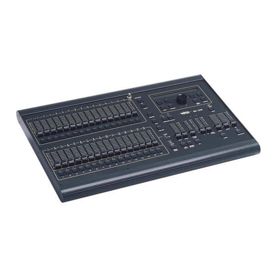
Console SNAPSHOT ================ NSI ================= MC 7516 Rel 1.29 CLEAR HELP CHANGE MAIN CANCEL MENU RECORD SOLO MC 7516 EDIT DIRECTION ATTACK MODE PREVIEW SUBS 17-32 RATE LEVEL STACK SUBS LEVEL BUMP KILL FADE 17-32 SOLO BUMP CHASE AUDIO BLACKOUT MODE SYNC SELECT... - Page 7 6. Scene Bump Buttons: These 16 (24) [32] buttons control the memory scene on the current page of memory. These buttons can bring the scene to full intensity (normal bump mode), toggle the scene OFF and ON (toggle mode), allow only one button to toggle at a time (kill mode), or solo the scene by turning all other controller output OFF (solo mode).
- Page 8 22. Audio Button: This button toggles the audio mode ON and OFF. When the LED above the button is lit, the audio mode is active. 23. Bump Master Slider: This slider controls the intensity of the channel bump buttons always, and the submaster bump buttons when they are in the normal bump mode only.
-
Page 9: Rear Panel (All Models)
It is important that the voltage selector is set for the correct voltage. Fuses should only be replaced with ones of same type and rating. 2. Micro-plex Outputs: These 2 outputs provide Leviton microphone dimmer connection via a 3-pin XLR type connector. Either connector may be used. 3. DMX512: This optically isolated output is used to provide dimmer control information to dimmers using this protocol. -
Page 10: Installation And Setup
0.8 A and at least the nominal operating voltage of that country. The mating connector to the console is a female IEC 320, Sheet C13 connector rated 10A, 250V. Dimmer Equipment Connection Connecting the N7500 Series console to Leviton dimming equipment is very simple. You need only to connect a Female Micro-plex... -
Page 11: Configuration
Configuration General The Setup function button of the LCD main menu is used to access the console configuration. All setup information is stored in nonvolatile memory. Stack Step Fade Page Setup *<* 0:00.0 Locked: If the console is locked, then a key code will have to be entered (6157 or 4257 or 2357) Setup parameters are locked. -
Page 12: Dimmer/Memory Menu
Clearing Patch: Pressing the Clr function will completely zero out all patch information for the active patch in nonvolatile memory, leaving a blank or empty patch to start with. A confirmation screen will appear on the LCD, select Yes to proceed or No to cancel and return to the previous screen. -
Page 13: Midi Menu
Preheat Max Dims Size More Dimmer Output Mode: Pressing the Out function button will select the type of dimmer output. Available options are MCX (Micro-plex with DMX512) or DMX (DMX512 only, full speed). Other options may be purchased for the controller and are discussed in information provided with the options. -
Page 14: Real Time Clock
MIDI Save Exit Select Memory: Use the “Mem” function button to select the type of memory to save. For each type of memory displayed, use the Yes/No function button to select it. Several types may be selected at a time. Start Dump: Press the Save button when the MIDI device is ready to accept the memory dump. -
Page 15: Operation
Operation General The N7500 Series Lighting Console has the basic features of two manual scenes mastered by two split/dipless crossfaders, individual channel bump buttons, programmable chase effects, a master control and a blackout button. Several record/edit features are provided as well as a menu driven LCD and help system. The console is designed to allow tailoring to your needs. -
Page 16: Using Chase
In Wide Mode (expanded channels or sngl scn), the Scene B Sliders control these additional channels; N7516: channels 17 - 32, N7524: channels 25 - 48, N7532: channels 33 - 64. The B Crossfader becomes a master for these additional channels with maximum level at the top of the slider movement. The following conditions apply to wide mode operation: •... -
Page 17: Using Cue Stack
Example: Modify Chase number one (Chase #1 must be running as above example). 1. Press button to change direction. DIRECTION 2. Press button to change attack. ATTACK 3. Move Chase Rate or press button to change rate. SYNC To cancel the chase running in the chaser, press the CHASE SELECT followed by pressing the BLACKOUT button. - Page 18 An asterisk in the STEP field indicates that the selected stack is empty (i.e.. 12:* where there are no steps programmed for this stack). An asterisk alone without a STACK:STEP field indicates that the stack has been cleared (i.e.. 1:8<* where the next step is a cleared stack). The Stack may be selected as a stack number from 1 to 16 by pressing the Stack function button of the LCD display.
-
Page 19: Snapshot
Example: Clear Stack 1 (assuming Stack 1 set as above example). 1. Press Clear Function button (next stack shows *). Stack Step Fade Page Setup 1:2<* 0:00.0 2. Press STACK FADE button (stack shows *<*). Stack Step Fade Page Setup *<* 0:00.0 Substitute moving the Stack Fade crossfader instead of pressing the Stack Fade GO button in the above... -
Page 20: Grand Master
Grand Master The Grand Master (GM) slide control provides proportional level control over all controller functions to stage with the exception of the Bump buttons. For example, whenever the Master Slide control is at minimum, all stage outputs will be at zero except for any resulting from a Bump button press. -
Page 21: Programming
Programming General To initiate programming, first tap the RECORD button. This will light the RECORD LED indicating that the program mode is active. Then tap the function button to be programmed. All programming is stored in nonvolatile memory, which retains information for at least 10 years, even when power is removed. Memory Pages Depending on how the memory is configured, there are 8 or 16 pages of memory. -
Page 22: Previewing Submasters
Previewing Submasters Submasters memories may be previewed on the Channel Level LEDs without affecting anything on stage. Pressing the PREVIEW button to activate the preview mode does this. The preview mode is active whenever the LED above the PREVIEW button is lit. Now pressing any Submaster Bump button will cause the scene contained in the submaster to display on the Channel Level LEDs and the percentages of each channel will be displayed on the LCD. -
Page 23: Recording Chases
3. Using the Scene A slide controls, slowly move channel 1 slider from minimum to full until a match is made. 4. Then move the slider to a new level. P: 1 8 Chs S: 1 0 100 0 100 0 100 5. - Page 24 CHASE 2. Press Select button. SELECT Record Chase 3. Select chase number 2 on the LCD and select Do Rec. Record Chase 4. If chase is not empty, select Yes. Chase is not empty! Clear? Attk Rec Chase: 2 -> Step: Step 5.
-
Page 25: Recording Cue Stacks
If the Chase is active when programming is initiated, the Chase will halt during programming and resume with the new programming when completed. If the Chase was not active, it will not be running when programming is complete. Recording Cue Stacks Cue Stacks are a collection of scenes and chases that are already programmed in the submaster memories. -
Page 26: Midi
MIDI MIDI Show Control Format: <sys ex = F0H><real time = 7FH><dev ID><msc = 02><lighing = 01 ><command><data><end sys ex = F7H> Receives: Command: 1: Go - Starts current step of active stack or loads stack and step indicated in the data field and executes. Data (optional): nn ... -
Page 27: Note On
Control: 1028 = Fade Rate Value: 0 - 1200, Seconds = Value / 10 Note On Format: <note on = 9cH, c = MIDI chan><note num = 0 - 127><veloc = 1 - 127> Receives: Notes 0 - 63 map to channels 1 - 64. Velocity field sets level of channel with 0 representing off and 127 representing full on. - Page 28 Troubleshooting Channel Level LEDs do not respond. • Check to see if 1 x 32 (1 x 48) [1 x 64] mode is selected. Since all channels cannot be viewed, the LEDs are disabled in this mode. • C h a s e f u n c t i o n s d o n o t w o r k . Make sure a rate has been established with the TAP SYNC button or chase rate slider.
- Page 29 Chases: 16 (24) [32) 400 steps total. 203 steps in Wide Mode. Memory: Non-volatile EEPROM (approx. 10 year retention). Dimmer Outputs: Leviton Micro-plex. DMX512. MIDI: In / Out / Thru Input Power: 120 / 240 Volts AC, 1A. Dimensions (L x W x H): 23"...
- Page 30 Notes Page 30 of 32...
- Page 31 Page 31 of 32...
- Page 32 Leviton warrants to the original consumer purchaser and not for the benefit of anyone else that this product at the time of its sale by Leviton is free of defects in materials and workmanship under normal and proper use for two years from the purchase date.
Need help?
Do you have a question about the N7516 and is the answer not in the manual?
Questions and answers