Table of Contents

Related Manuals for Case IH FARMALL 35A


Summary of Contents for Case IH FARMALL 35A
- Page 1 FARMALL ® FARMALL ® Tier 4B (final) Compact Tractor FARMALL ROPS: PIN LSMF35ARxx0010001 to LSMF35ARVH0010035 ® FARMALL ROPS: PIN LSMF40ARxx0010001 to LSMF40ARCH0010034 ® SERVICE MANUAL Part number 48144025 edition English June 2017...
- Page 2 SERVICE MANUAL Farmall® 35A Tier 4B (final), ROPS [LSMF35ARxx0010001 - LSMF35ARVH0010035] Farmall® 40A Tier 4B (final), ROPS [LSMF40ARxx0010001 - LSMF40ARCH0010034] 48144025 23/06/2017 Find manuals at https://best-manuals.com...
- Page 3 Link Product / Engine Product Market Product Engine Farmall® 35A Tier 4B (final), North America L3C19-T5 ROPS [LSMF35ARxx0010001 - LSMF35ARVH0010035] Farmall® 40A Tier 4B (final), North America L3C19-T4 ROPS [LSMF40ARxx0010001 - LSMF40ARCH0010034] 48144025 23/06/2017 Find manuals at https://best-manuals.com...
- Page 4 Contents INTRODUCTION Engine..................10 [10.001] Engine and crankcase ............. 10.1 [10.216] Fuel tanks .
- Page 5 [25.102] Front bevel gear set and differential ..........25.2 [25.108] Final drive hub, steering knuckles, and shafts .
- Page 6 Hitches, drawbars, and implement couplings........37 [37.100] Drawbars and towing hitches ............37.1 [37.108] Rear three-point hitch external controls .
- Page 7 [90.114] Operator protections ............. . . 90.2 [90.120] Mechanically-adjusted operator seat.
- Page 8 INTRODUCTION 48144025 23/06/2017 Find manuals at https://best-manuals.com...
-
Page 9: Table Of Contents
Contents INTRODUCTION Foreword - Important notice regarding equipment servicing ........3 Foreword . -
Page 10: Foreword - Important Notice Regarding Equipment Servicing
Specifications, descriptions, and illustrative material herein are as accurate as known at time of publication but are subject to change without notice. In case of questions, refer to your CASE IH Sales and Service Networks. 48144025 23/06/2017... -
Page 11: Foreword
50B tractors. Use this manual in conjunction with the operator's manual for complete operation, adjustment, and maintenance information On CASE IH equipment, left and right are determined by standing behind the unit, looking in the direction of travel. 48144025 23/06/2017... -
Page 12: Safety Rules
INTRODUCTION Safety rules Personal safety This is the safety alert symbol. It is used to alert you to potential personal injury hazards. Obey all safety messages that follow this symbol to avoid possible death or injury. Throughout this manual you will find the signal words DANGER, WARNING, and CAUTION followed by special in- structions. -
Page 13: Safety Rules
INTRODUCTION Safety rules BT09A213 48144025 23/06/2017... -
Page 14: Safety Rules - Personal Safety
INTRODUCTION Safety rules - Personal safety General safety rules Read this manual carefully before starting, using carrying out maintenance, refueling or performing any other type of operation on the tractor. Read all the safety decals on the tractor and follow the instructions thereon before starting, operating, refueling or carrying out maintenance on the tractor. - Page 15 INTRODUCTION Before starting the tractor, be sure that all controls are in neutral or park lock position. Before starting the engine, make sure that all attached implements are lowered to the ground. Start the engine only from the operator’s seat. If the safety start switch is bypassed, the engine can start with the transmission in gear.
- Page 16 INTRODUCTION Before leaving the tractor: 1. Park tractor on a firm level surface. 2. Put all controls in neutral or park lock position. 3. Engage park brake. Use wheel chocks if required. 4. Lower all hydraulic equipment — Implements, header, etc. 5.
- Page 17 INTRODUCTION Unsupported hydraulic cylinders can lose pressure and drop the equipment causing a crushing hazard. Do not leave equipment in a raised position while parked or during service, unless securely supported. Jack or lift the tractor only at jack or lift points indicated in this manual. Incorrect towing procedures can cause accidents.
- Page 18 INTRODUCTION Replace damaged or worn tubes, hoses, electrical wiring, etc. Engine, transmission, exhaust components, and hydraulic lines may become hot during operation. Take care when servicing such components. Allow surfaces to cool before handling or disconnecting hot components. Wear protective equipment when appropriate.
- Page 19 INTRODUCTION Make sure brake pedal latch is engaged. Brake pedals must be locked together for road travel. Use safety chains for trailed equipment when provided with tractor or equipment. Lift implements and attachments high enough above ground to prevent accidental contact with road. When transporting equipment or tractor on a transport trailer, make sure it is properly secured.
- Page 20 INTRODUCTION Using implements and agricultural machinery 1. Do not connect implements or machinery that require more power than can be generated by your tractor model. 2. Never negotiate sharp turns with the power take-off under a heavy load; this may damage the universal joints on the transmission shaft connected to the power take-off.
- Page 21 INTRODUCTION Battery post, terminals, and related accessories contain lead and lead compounds. Wash hands after handling. This is a California Proposition 65 warning. Battery acid causes burns. Batteries contain sulfuric acid. Avoid contact with skin, eyes, or clothing. Antidote (ex- ternal): Flush with water.
- Page 22 INTRODUCTION • Clean belts only with soap solution and warm water. • Do not use bleach or dye on the belts because this can make the belts weak. • For proper seat belt use, see the Operator’s Manual. 48144025 23/06/2017...
- Page 23 INTRODUCTION Operator protective structure Your tractor is equipped with an operator protective structure, such as: a Roll Over Protective Structure (ROPS), Falling Object Protective Structure (FOPS), or a cab with ROPS. A ROPS may be a can frame or a two-posted or four-posted structure used for the protection of the operator to minimize the possibility of serious injury.
- Page 24 INTRODUCTION Personal Protective Equipment (PPE) Wear Personal Protective Equipment (PPE) such as hard hat, eye protection, heavy gloves, hearing protection, pro- tective clothing, etc. Do Not Operate tag Before you start servicing the tractor, attach a ‘Do Not Operate’ warning tag to the tractor in an area that will be visible. Hazardous chemicals If you are exposed to or come in contact with hazardous chemicals you can be seriously injured.
- Page 25 INTRODUCTION Electrical storm safety Do not operate tractor during an electrical storm. If you are on the ground during an electrical storm, stay away from machinery and equipment. Seek shelter in a permanent, protected structure. If an electrical storm should strike during operation, remain in the cab. Do not leave the cab or operator’s platform. Do not make contact with the ground or objects outside the tractor.
-
Page 26: Torque - Minimum Tightening Torques For Normal Assembly
INTRODUCTION Torque - Minimum tightening torques for normal assembly Metric non-flanged hardware Nom- Lock nut Lock nut inal class 8 with class 10 with size Class 8.8 bolt and class 8 Class 10.9 bolt and class class 8.8 class 10.9 10 nut bolt bolt... - Page 27 INTRODUCTION Metric flanged hardware Nom- Class 8.8 bolt and class 8 Class 10.9 bolt and class Lock nut Lock nut inal 10 nut class 8 with class 10 with size class 8.8 class 10.9 bolt bolt Plated with Plated with Unplated Unplated ZnCr...
- Page 28 INTRODUCTION 1. Manufacturer's identification 2. Property class 3. Clock marking of property class and manufacturer's identification (optional), i.e. marks 60° apart indicate Class 10 properties, and marks 120° apart indicate Class 8. Inch non-flanged hardware Lock nut Lock nut SAE Grade 5 bolt and SAE Grade 8 bolt and Nominal size Grade B with...
- Page 29 INTRODUCTION Inch flanged hardware Nom- Lock nut Lock nut inal SAE Grade 5 bolt and nut SAE Grade 8 bolt and nut Grade F with Grade G with size Grade 5 bolt Grade 8 bolt Unplated Unplated or Plated with Plated with or plated plated Silver...
- Page 30 INTRODUCTION Inch lock nuts, all metal (three optional methods) 20090268 Grade identification Grade Corner marking method (1) Flats marking method (2) Clock marking method (3) Grade A No notches No mark No marks Grade B One circumferential notch Letter B Three marks Grade C Two circumferential notches...
-
Page 31: Torque - Standard Torque Data For Hydraulic Connections
Over-torquing of a hydraulic connection can also lead to leakage or failure. For some connections, CASE IH requires a different torque value than is listed in the ISO and SAE standards. • The torque values in this document should be used whenever possible or applicable. - Page 32 INTRODUCTION Torque values for metric O-Ring Boss (ORB) port connections S-Series * L-Series ** Metric Ferrous Non-Ferrous Ferrous Non-Ferrous thread N·m (lb ft) ± 10% N·m (lb ft) ± 10% N·m (lb ft) ± 10% N·m (lb ft) ± 10% M8 x 1 10.5 (7.7) 6.3 (4.6)
- Page 33 INTRODUCTION Torque values for port connections (British Standard Pipe Parallel (BSPP) thread ports and stud ends) Metric tube Outside Diameter (OD) Ferrous Non-Ferrous mm (in) BSPP S-Series L-Series S-Series L-Series thread S-Series * L-Series ** N·m (lb ft) N·m (lb ft) N·m (lb ft) N·m (lb ft) G- Gas;...
- Page 34 INTRODUCTION Torque values for Inch O-Ring Boss (ORB) port non-adjustable connections S-Series * L-Series ** Ferrous Non- Ferrous Non- Inch tube UN/UNF N·m (lb ft) Ferrous N·m (lb ft) Ferrous dash size thread size ± 10% N·m (lb ft) ± 10% N·m (lb ft) mm (in) ±...
- Page 35 INTRODUCTION Torque values for inch O-Ring Boss (ORB) port plugs Ferrous Non-Ferrous Internal hex External hex UN/UNF N·m (lb ft) N·m (lb ft) N·m (lb ft) dash size thread size ± 10% ± 10% ± 10% 5/16-24 7.5 (5.5) 12.5 (9.2) 7.5 (5.5) 3/8-24 14.5 (10.7)
- Page 36 INTRODUCTION Torque values for four-bolt flange connections (Inch Screws, Grade 8) Code 61 Code 62 Metric size Imperial size Screw code Screw code N·m (lb ft) N·m (lb ft) ± 10% ± 10% 5/16-18 34 (25.1) 5/16-18 34 (25.1) 3/8-16 63 (46.5) 3/8-16 63 (46.5)
- Page 37 INTRODUCTION Torque values for O-Ring Face Seals (ORFS) connections Hex size Metric Swivel nut Swivel nut Inch tube (mm) UN/UNF tube dash torque torque OD (mm) (Reference thread size OD (mm) size N·m (lb ft) N·m (lb ft) only) ± 10% ±...
-
Page 38: Basic Instructions - Shop And Assembly
Only use CNH Original Parts or CASE IH Original Parts. Only genuine spare parts guarantee the same quality, duration, and safety as original parts, as they are the same parts that are assembled during standard production. Only CNH Original Parts or CASE IH Original Parts can offer this guarantee. - Page 39 The special tools that CASE IH suggests and illustrate in this manual have been specifically researched and designed for use with CASE IH machines. The special tools are essential for reliable repair operations. The special tools are accurately built and rigorously tested to offer efficient and long-lasting operation.
-
Page 40: General Specification - Biodiesel Usage
The use of non-approved fuels may void CASE IH Warranty coverage. - Page 41 See the National Biodiesel Board website at www.biodiesel.org for more information. The use of biodiesel blends above B5 through B20 will not void the CASE IH warranty as long as the following con- ditions for biodiesel fuel handling and maintenance are stringently followed: Biodiesel fuel must be pre-blended by the supplier.
- Page 42 Regular oil sampling is highly recommended to monitor for oil and engine deterioration. NOTE: Oil sampling kits are available from your authorized CASE IH dealer. When switching back from biodiesel to regular #2 diesel, all fuel filter, oil and oil filter should be changed even if this falls between routine service intervals.
-
Page 43: Consumables
INTRODUCTION Consumables Lubricant Type and Description Part Number Container Size 0.946 l (1 US qt) 9613313 CASE IH AKCELA NO. 1™ ENGINE OIL CJ-4 SAE 86641052 3.785 l (1 US gal) 10W-30 9673508 18.93 l (5 US gal) Engine Oil API CJ-4 0.946 l (1 US qt) -
Page 44: General Specification
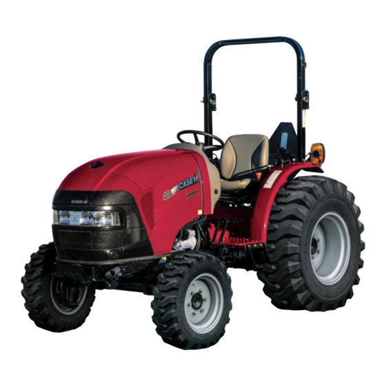
INTRODUCTION General specification Model Model Farmall® 35A Farmall® 40C Farmall®40A Hydrostatic/Mechanical Hydrostatic/Mechanical Engine Type Diesel Diesel Model L3C19-T5 L3C19–T4 Emission level (tier) Tier 4B (final) Tier 4B (final) Aspiration Turbo Turbo Engine gross horsepower 26 kW (35 Hp) 29 kW (39 Hp) Cylinders Bore 88.000 mm (3.465 in) - Page 45 INTRODUCTION Model Model Farmall® 35A Farmall® 40C Farmall®40A Hydrostatic/Mechanical Hydrostatic/Mechanical Alternator 12 V, Heavy duty, 70 A 12 V, Heavy duty, 70 A Battery 12 V, w/ negative ground, 80 / 660 12 V, w/ negative ground, 80 / 660 cca cca BCI Group 34 BCI Group 34 Starting motor...
- Page 46 INTRODUCTION Model Model Farmall® 35A Farmall® 40C Farmall®40A Hydrostatic/Mechanical Hydrostatic/Mechanical Type Latch Latch Location Seat side Seat side Actuation Mechanical Mechanical Number of plates Lever latching Cable activated Cable activated Steering Type Power Power Turns lock-to-lock: 2.86 L to R 2.86 L to R 2.89 R to L 2.89 R to L...
- Page 47 INTRODUCTION Model Model Farmall® 35A Farmall® 40C Farmall®40A Hydrostatic/Mechanical Hydrostatic/Mechanical Transmission speeds (Hydrostatic) ( 2600 RPM Engine rated speed with ( 2600 RPM Engine rated speed with 11.2-24 Rear tires) 11.2-24 Rear tires) Gear position: 0 – 5.23 km/h (0 – 3.251 mph) 0 –...
- Page 48 INTRODUCTION Model Model Farmall® 35A Farmall® 40C Farmall®40A Hydrostatic/Mechanical Hydrostatic/Mechanical Adjustable Standard Standard Max permissible towing weight and max load Max permissible towing weight, lbs 1300 kg (2866 lb) 1300 kg (2866 lb) (kg) Max load, Kg, (lbs.), drawbar in 730 kg (1609 lb) 730 kg (1609 lb) short position...
-
Page 49: Dimension - Roll Over Protection System (Rops)
INTRODUCTION Dimension - Roll Over Protection System (ROPS) Farmall® 35C Farmall® 40C (1) - Minimum ground clearance (under drawbar): Ag. tires: 330.5 mm (13.0 in) 330.5 mm (13.0 in) 11.2-24 Turf tires: 300.0 mm (11.8 in) 300.0 mm (11.8 in) 41 x 14.00-20 Ind. - Page 50 INTRODUCTION Farmall® 35C Farmall® 40C Ind. tires: 43 x 16-20 Up position 2354 mm (92.7 in) 2354 mm (92.7 in) (7) - Wheel base: 1674 mm (66 in) 1674 mm (66 in) (8) - Length: FWD: 3023 mm (119 in) 3023 mm (119 in) Weight with ROPS / less tires: HST (FWD)
-
Page 51: Product Identification - Machine Orientation
This as a preview PDF file from best-manuals.com Download full PDF manual at best-manuals.com...
Need help?
Do you have a question about the FARMALL 35A and is the answer not in the manual?
Questions and answers