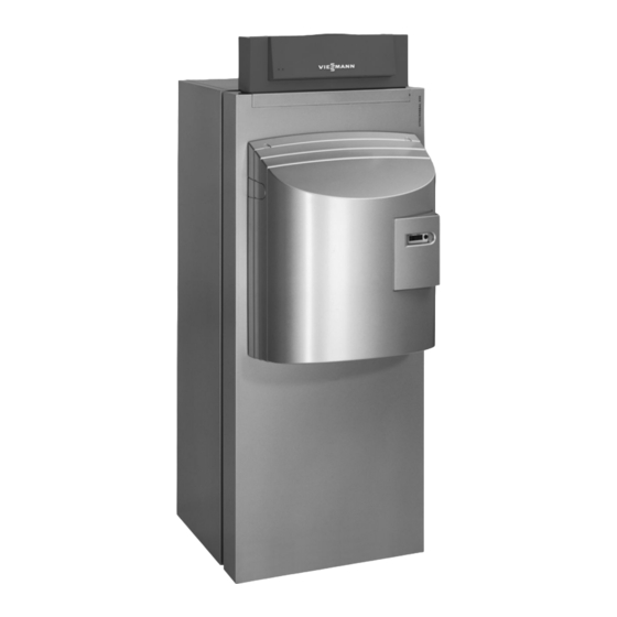
Viessmann Vitocrossal 300 Installation Instructions Manual
Gas condensing boiler with matrix radiant burner
Hide thumbs
Also See for Vitocrossal 300:
- Service instructions manual (164 pages) ,
- Service instructions for contractors (148 pages) ,
- Service manual (108 pages)
Subscribe to Our Youtube Channel
Summary of Contents for Viessmann Vitocrossal 300
-
Page 1: Installation Instructions
VIESMANN Installation instructions for contractors Vitocrossal 300 Type CM3 Gas condensing boiler with MatriX radiant burner VITOCROSSAL 300 Dispose after installation. 5862 417 GB 11/2014... -
Page 2: Safety Instructions
Safety instructions Please follow these safety instructions closely to prevent accidents and material losses. Safety instructions explained Please note This symbol warns against the risk of material losses and environmental pollution. Note Details identified by the word "Note" contain additional information. -
Page 3: Table Of Contents
Index Information Symbols ....................Intended use ..................Clearance dimensions ................Installation sequence Siting and levelling the boiler ..............Fitting the thermal insulation ..............Connections on the heating water side ..........Safety connections ................Making connections on the flue gas side ..........Exhaust gas connection .............. -
Page 4: Information Symbols
Symbols Symbol Meaning Reference to other document containing further information Additional information, not safety relevant Step: The numbering corresponds to the se- quence of work. Intended use The appliance is only intended to be installed and Any usage beyond this must be approved by the man- operated in sealed unvented heating systems that ufacturer in each individual case. -
Page 5: Installation Sequence Siting And Levelling The Boiler
Siting and levelling the boiler Please note Note Damage to the flue outlet can result in leaks. A suitable condensate drain (maximum 50 mm above Never lift or move the boiler by the flue outlet. floor level) must be available in the installation room if the boiler is installed at ground level. -
Page 6: Fitting The Thermal Insulation
Fitting the thermal insulation Note All components required for fitting the thermal insula- tion can be found in the box with the thermal insula- tion. Fig.3... - Page 7 Fitting the thermal insulation (cont.) 90° Fig.4...
-
Page 8: Connections On The Heating Water Side
Connections on the heating water side Fig.5 Safety connection (safety valve and air vent valve) Boiler return 2 PN 6 DN 40 ¼ Boiler flow PN 6 DN 50 Boiler return 1 Female connection for control equipment R PN 6 DN 50 ½... -
Page 9: Making Connections On The Flue Gas Side
Safety connections (cont.) Low water indicator Note Equip boilers with a safety valve that is type-tested Tests have verified that the low water indicator speci- according to TRD 721 [or local regulations] and is fied by EN 12828 is not required. identified in accordance with the relevant system. -
Page 10: Mounting The Thermal Insulation And Control Unit
Mounting the thermal insulation and control unit Note Boiler water temperature sensor is supplied in the § control unit pack. Burner cable and extension together with plug lÖ are supplied in a separate pack. Insert the sensor and boiler water temperature sensor as far as they will go into the sensor well. - Page 11 Mounting the thermal insulation and control unit (cont.) 3.9 x 20 Fig.9...
- Page 12 Mounting the thermal insulation and control unit (cont.) 90° 8. 3. Fig.10 Bundle the cables and secure them to the side panel with cable ties.
-
Page 13: Mounting The Burner
Mounting the thermal insulation and control unit (cont.) 3,9 x 9,5 Fig.11 Boiler type plate Mounting the burner Burner installation instructions Commissioning and adjustment Service instructions for boiler, burner and boiler control unit... - Page 16 Viessmann Werke GmbH&Co KG Viessmann Limited D-35107 Allendorf Hortonwood 30, Telford Telephone: +49 6452 70-0 Shropshire, TF1 7YP, GB Fax: +49 6452 70-2780 Telephone: +44 1952 675000 www.viessmann.com Fax: +44 1952 675040 E-mail: info-uk@viessmann.com...


Need help?
Do you have a question about the Vitocrossal 300 and is the answer not in the manual?
Questions and answers