Table of Contents
Advertisement
Quick Links
Advertisement
Table of Contents

Related Manuals for Dell EMC PowerSwitch S5148F-ON


Summary of Contents for Dell EMC PowerSwitch S5148F-ON
- Page 1 Dell EMC PowerSwitch S5148F-ON Installation Guide July 2021 July 2021 Rev. A04...
- Page 2 A WARNING indicates a potential for property damage, personal injury, or death. © 2017 - 2021 Dell Inc. or its subsidiaries. All rights reserved. Dell, EMC, and other trademarks are trademarks of Dell Inc. or its subsidiaries. Other trademarks may be trademarks of their respective owners.
-
Page 3: Table Of Contents
Contents Chapter 1: About this guide......................5 Related documents................................5 Information symbols................................6 Chapter 2: S5148F-ON switch....................... 7 Introduction................................... 7 Features....................................8 Physical dimensions................................8 LED display.................................... 8 LED behavior...................................9 Prerequisites..................................11 S5148F-ON switch configurations..........................11 Luggage tag..................................12 Chapter 3: Site preparations......................13 Site selection..................................13 Cabinet placement................................ - Page 4 USA Federal Communications Commission statement..................... 41 European Union EMC directive conformance statement..................41 Japan VCCI compliance for class A equipment......................42 Korean certification of compliance..........................42 Safety standards and compliance agency certifications..................43 Electromagnetic compatibility ............................43 Product recycling and disposal............................43 Chapter 10: Dell EMC support......................45 Contents...
-
Page 5: Chapter 1: About This Guide
● OS10 Enterprise Edition User Guide ● OS10 Enterprise Edition Release Notes ● S5148F-ON Set-up Guide ● S5148F-ON Release Notes ● Open Networking Hardware Diagnostic Guide NOTE: For the most recent documentation, see the Dell EMC support site: www.dell.com/support. About this guide... -
Page 6: Information Symbols
Information symbols This book uses the following information symbols: NOTE: The Note icon signals important operational information. CAUTION: The Caution icon signals information about situations that could result in equipment damage or loss of data. NOTE: The Warning icon signals information about hardware handling that could result in injury. NOTE: The ESD Warning icon requires that you take electrostatic precautions when handling the device. -
Page 7: Chapter 2: S5148F-On Switch
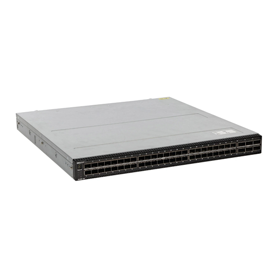
S5148F-ON switch The following sections describe the Dell EMC S5148F-ON switch: Topics: • Introduction • Features • Physical dimensions • LED display • Prerequisites • S5148F-ON switch configurations • Luggage tag Introduction The S5148F-ON switch is a one rack unit, full-featured, fixed form-factor top-of-rack (ToR) compact 10/25/40/50/100GbE switch. -
Page 8: Features
Figure 3. SS5148F-ON switch PSU-side view 1. PSU1 2. Fan Modules 1 and 2 3. RJ-45 management port 4. Luggage Tag 5. Fan Modules 3 and 4 6. PSU2 7. USB Type A 8. MicroUSB-B Port 9. RS-232 console port Features The S5148F-ON switch offers the following features: ●... -
Page 9: Led Behavior
LED behavior The following S5148F-ON switch LED behavior is seen during open networking installation environment (ONIE) operations: S5148F-ON LEDs 1. Stack ID LED 2. Port Activity LED 3. Port Activity LED 4. Master LED 5. System LED 6. Locator LED 7. - Page 10 Table 1. S5148F-ON switch LED behavior (continued) Description ● Blinking yellow—Power supply failed Master LED ● Off—Switch is in Stacking Slave mode ● Solid green—Switch is in Stacking Master or Standalone mode FAN LED ● Off—No power ● Solid green—Normal operation; fan powered and running at the expected RPM ●...
-
Page 11: Prerequisites
Table 4. QSFP28 port LEDs Description Link/Activity LED—100G, 40G, or 10G ● Off—No link ● Solid green—Link operating at maximum speed, 100G for QSFP28 port ● Flashing green—Port activity operating at maximum speed, 100G for QSFP28 ports ● Solid yellow—Port activity operating at a lower speed, 40G or 10G port ●... -
Page 12: Luggage Tag
● AC or DC power supply with airflow from the I/O side to the PSU side—normal airflow. ● AC or DC power supply with airflow from the PSU side to the I/O side—reverse airflow. Luggage tag The switch has a pull-out tag, known as a luggage tag, on the PSU-side of the switch. The front of the luggage tag includes switch ID information. -
Page 13: Chapter 3: Site Preparations
Site preparations The S5148F-ON switch is suitable for installation as part of a common bond network (CBN). You can install the switch in: ● Network telecommunication facilities ● Data centers ● Other locations where the National Electric Code (NEC) applies For more information about switch specifications, see Specifications. -
Page 14: Rack Mounting
Rack mounting When you prepare your equipment rack, ensure that the rack is grounded. Ground the equipment rack to the same ground point the power service in your area uses. The ground path must be permanent. Fans and airflow The S5148F-ON switch fans support two airflow options: normal and reverse. Fan combinations Fan installation is done as part of the factory install based on stock keeping unit (SKU) type. -
Page 15: Chapter 4: Nebs Compliance
NEBS-compliant ground installation Before you install the switch into a rack, install the ground (GND) lug assembly. Your switch includes an assembled UL-certified GND lug with bracket, packaged separately. If any parts are missing, contact your Dell EMC Sales Representative. NEBS compliance... - Page 16 Figure 5. GND lug assembly 1. Remove the two installed M3 screws from the lower-left side of your switch. NOTE: Keep these screws. 2. Remove the bracket assembly from the shipping bag. 3. Clean the bracket and lug surfaces thoroughly and apply an anti-oxidant solution to the mating surfaces. 4.
- Page 17 Figure 7. GND lug assembly attached 6. Install your switch into your rack using the S5148F-ON switch installation instructions. NEBS compliance...
-
Page 18: Chapter 5: S5148F-On Switch Installation
S5148F-ON switch installation To install the S5148F-ON switch, complete the installation procedures in the order presented in this section. Always handle the switch and components with care. Avoid dropping the switch or its field replaceable units (FRUs). NOTE: ESD damage can occur if components are mishandled. Always wear an ESD-preventive wrist or heel ground strap when handling the S5148F-ON switch and components. -
Page 19: Readyrails Installation
● Do not mount the equipment with the back panel facing downward. ReadyRails installation To easily configure your rack for installation of your S5148F-ON switch, use the ReadyRails rack mounting system provided. You can install the ReadyRails system using the 1U tool-less method or one of three possible 1U tooled methods—two-post flush mount, two-post center mount, or four-post threaded mount. -
Page 20: Two-Post Flush-Mount Installation
Figure 9. 1U tool-less nonthreaded square hole installation 2. Align and seat the front flange pegs in the holes on the front side of the vertical post. NOTE: Be sure that the rails click into place and are secure. 3. Repeat this procedure for the second rail. To remove each rail, pull on the latch release on each flange ear and unseat each rail. -
Page 21: Two-Post Center-Mount Installation
Figure 10. Two-post flush-mount configuration 2. Attach one rail to the front post flange with two user-supplied screws. See item 2. 3. Slide the plunger bracket forward against the vertical post and secure the plunger bracket to the post flange with two user-supplied screws. -
Page 22: Four-Post Threaded Installation
Figure 11. Two-post center-mount threaded round-hole installation 2. Slide the back bracket towards the post. Secure it to the post flange with two user-supplied screws. See item 2 and 3. 3. Repeat this procedure for the second rail. Four-post threaded installation NOTE: For more installation instructions, see the installation labels attached to the rail assembly. -
Page 23: Switch Installation
Figure 12. Four-post threaded round-hole installation 2. For each rail, attach the front and back flanges to the post flanges with two user-supplied screws at each end. Switch installation You can mount the switch in the 1U front-rack or 1U two-post, flush or center configuration. The following is an example of a front-rack configuration: For the 1U two-post configurations, slide the switch into the rails in the same manner as the four-post configurations. - Page 24 Figure 13. Attach switch rail 2. After installing both switch rails, line them up on the previously mounted ReadyRails and slide the switch in until it is flush with front of rack. To keep the switch from inadvertently sliding out of the rack and falling, about 3 inches before you fully insert your switch, the rail locking feature engages.
-
Page 25: Ground Cable
● Two threaded holes using one of the two M4 screws. In both configurations, the ground cable is not included. To properly ground the switch, Dell EMC recommends a one- or two-hole lug, M3 or M4 hole size. The grounding lugs must be a UL-recognized, crimp-type lug. -
Page 26: Optics Removal
● If you need ONIE information, see ONIE documentation at www.onie.org. ● If you are using third-party software, see your third-party software documentation. Switch replacement The following steps describe removing and replacing a switch. For further assistance when replacing a switch, contact your Dell EMC support representative. NOTE: ESD damage can occur when components are mishandled. - Page 27 4. Remove the switch from the rack. At the same time, press in the two side-release bars on the switch and slide the switch forward. If you are using the fan trays or PSUs in the replacement switch, remove them from the switch. 5.
-
Page 28: Chapter 6: Power Supplies
Power supplies The S5148F-ON switch ships with two AC or DC power supplies. The two power supplies have two air-flow directions—from the I/O to the PSU and from the PSU to the I/O. Two PSUs are required for full redundancy, but the switch can operate with a single PSU. The PSUs are field replaceable. -
Page 29: Ac Or Dc Power Supply Installation
CAUTION: Remove the power cable from the PSU before removing the PSU. Also, do not connect the power cable before you insert the PSU in the switch. NOTE: To comply with the GR-1089 Lightning Criteria for Equipment Interfacing with AC or DC Power Ports, use an external surge protection device (SPD) at the AC or DC input of the router. -
Page 30: Ac Or Dc Power Supply Replacement
NOTE: If a PSU fails, you must replace the entire unit. There are no field serviceable components in the PSU. To request a hardware replacement, see Dell EMC support. NOTE: If you use a single PSU, install a blank plate in the other PSU slot. If you are only using one power supply, install the power supply in the first slot, PSU1. - Page 31 WARNING: Do not cross the wires. In the wiring block, RTN aligns with RTN and –48V aligns with –48V. 5. Insert the DC power connector into the power socket of the DC PSU. Ensure that the connector pins firmly seat and you hear the click of the power connector’s left and right levered clamps lock into place.
-
Page 32: Chapter 7: Fans
Fans The S5148F-ON switch comes from the factory with two PSUs and four fan modules installed in the switch. The fan modules and the power supplies, which have integrated fans, are hot-swappable. In addition to the power supply modules, you can order and install fan modules separately. The S5148F-ON switch supports two airflow direction options. -
Page 33: Fan Module Installation
Figure 19. Fan module installation ● 1—Fan module Fan module replacement To request a hardware replacement, see Dell EMC support. CAUTION: Complete the following steps within one minute or the switch temperature could rise above safe thresholds and the switch could shut down: 1. - Page 34 2. Unlatch and remove the first module that needs the filter replaced. 3. Slide the existing filter upwards to remove it from the module. 4. Replace the filter with a new filter of the same size. 5. Reinsert the fan module. 6.
-
Page 35: Chapter 8: Management Ports
Management ports Besides the 10/100/1000Base-T RJ-45 ports, the S5148F-ON switch provides several ports for management and storage. NOTE: The output examples in this section are for reference only. Your output may vary. Topics: • RS-232 console port access • MicroUSB-B console port access •... -
Page 36: Microusb-B Console Port Access
MicroUSB-B console port access The MicroUSB-B console port is on the PSU side of the switch. NOTE: The S5148F-ON switch uses the Silicon Labs CP2109 USB-B chip. To find the correct USB-B universal asynchronous receiver-transmitter (UART) driver, see https://www.silabs.com/products/development-tools/software/ usb-to-uart-bridge-vcp-drivers. When you connect the microUSB-B port, it becomes the primary connection and, while connected, all messages are sent to the microUSB-B port. -
Page 37: Before You Install An Os
NOTE: For more information, see the Open Networking Hardware Diagnostic Guide. NOTE: After you have securely installed and powered on the S5148F-ON switch, to configure your switch, see your third-party ONIE-compatible OS or the Dell EMC OS documentation. Management ports... -
Page 38: Onie Service Discovery
ONIE service discovery ONIE attempts to locate the installer through several discovery methods, as shown. To download and run an installer, the ONIE Service Discovery feature uses the first successful method found. 1. Search locally attached storage devices for one of the ONIE default installer filenames—for example, the filename is: onie self update from the USB. -
Page 39: Chapter 9: Specifications
Specifications This section lists the S5148F-ON switch specifications. CAUTION: Operate the product at an ambient temperature not higher than 45°C (113°F). CAUTION: Lithium Battery Caution: There is a danger of explosion if the battery is incorrectly replaced. Replace only with same or equivalent type of battery. Dispose of the batteries according to the manufacturer's instructions. -
Page 40: Ieee Standards
470 W = 1603.7 BTU/Hr Maximum operational altitude 10,000 feet (3,048 meters) Maximum non-operational altitude 39,370 feet (12,000 meters) Shock Dell EMC Spec SV0115 Table 7. AC power requirements Parameter Specifications Power supply 100–240 VAC 50/60 Hz Maximum current draw per switch 4.7A/3.9A at 100/120V AC 2.35A/1.95A at 200/240V AC... -
Page 41: Agency Compliance
Properly shielded and grounded cables and connectors must be used in order to meet FCC emission limits. Dell EMC is not responsible for any radio or television interference caused by using other than recommended cables and connectors or by unauthorized changes or modifications in the equipment. -
Page 42: Japan Vcci Compliance For Class A Equipment
Equipment (VCCI). If this equipment is used in a domestic environment, radio disturbance may arise. When such trouble occurs, the user may be required to take corrective actions. NOTE: Use the AC power cords with Dell EMC equipment only. Do not use Dell EMC AC power cords with any unauthorized hardware. Figure 23. Japan: warning label Korean certification of compliance Figure 24. -
Page 43: Safety Standards And Compliance Agency Certifications
Product recycling and disposal You must recycle or discard this switch according to applicable local and national regulations. Dell EMC encourages owners of information technology (IT) equipment to responsibly recycle their equipment when it is no longer needed. Dell EMC offers a variety of product return programs and services in several countries to assist equipment owners in recycling their IT products. - Page 44 EEE on the environment and human health due to the potential presence of hazardous substances in EEE. Dell EMC products, which fall within the scope of the WEEE, are labeled with the crossed-out wheelie-bin symbol, as shown above, as required by WEEE.
-
Page 45: Chapter 10: Dell Emc Support
Dell EMC support The Dell EMC support site provides documents and tools to help you effectively use Dell EMC equipment and mitigate network outages. Through the support site you can obtain technical information, access software upgrades and patches, download available management software, and manage your open cases. The Dell EMC support site provides integrated, secure access to these services.
Need help?
Do you have a question about the EMC PowerSwitch S5148F-ON and is the answer not in the manual?
Questions and answers