Table of Contents
Advertisement
Quick Links
Advertisement
Table of Contents

Related Manuals for Dell PowerSwitch S5148F-ON


Summary of Contents for Dell PowerSwitch S5148F-ON
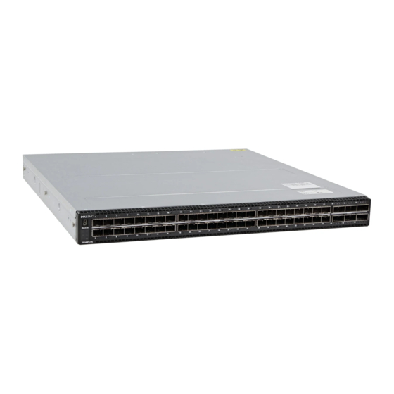
- Page 1 Dell EMC PowerSwitch S5148F-ON Set-up Guide March 2021 Rev. A01...
- Page 2 A WARNING indicates a potential for property damage, personal injury, or death. © 2017 - 2021 Dell Inc. or its subsidiaries. All rights reserved. Dell, EMC, and other trademarks are trademarks of Dell Inc. or its subsidiaries. Other trademarks may be trademarks of their respective owners.
-
Page 3: Table Of Contents
Contents Chapter 1: About this guide......................4 Related documents................................4 Information Symbols................................4 Chapter 2: Site preparations......................6 Site selection..................................6 Cabinet placement................................6 Rack mounting..................................7 Switch ground..................................7 Fans and airflow................................... 7 Power......................................7 Storing components................................7 Chapter 3: S5148F-ON switch Installation..................8 Unpack.................................... -
Page 4: Chapter 1: About This Guide
● Installation Guide for the S5148F-ON Switch ● Open Networking Hardware Diagnostic Guide ● Dell EMC S5148F-ON Switch Release Notes NOTE: For the most recent documentation, visit the support site: www.dell.com/support. Information Symbols This book uses the following information symbols: NOTE: The Note icon signals important operational information. - Page 5 NOTE: The ESD Warning icon requires that you take electrostatic precautions when handling the device. About this guide...
-
Page 6: Chapter 2: Site Preparations
Site preparations The S5148F-ON switch is suitable for installation as part of a common bond network (CBN). You can install the switch in: ● Network telecommunication facilities ● Data centers ● Other locations where the National Electric Code (NEC) applies For more information about the S5148F-ON switch specifications, see Specifications. -
Page 7: Rack Mounting
The ground path must be permanent. Switch ground Dell EMC recommends grounding your switch. Use the S5148F-ON switch in a CBN. Fans and airflow Fan installation is done as part of the factory install based on stock keeping unit (SKU) type. The S5148F-ON switch has SKUs that support the following configurations: ●... -
Page 8: Chapter 3: S5148F-On Switch Installation
S5148F-ON switch Installation To install the S5148F-ON switch, complete the installation procedures in the order presented in this section. Always handle the switch and its components with care. Avoid dropping the switch or any field replaceable units (FRUs). NOTE: ESD damage can occur if components are mishandled. Always wear an ESD-preventive wrist or heel ground strap when handling the switch and its components. -
Page 9: Rack Or Cabinet Installation
Rack or cabinet installation You may either place the switch on a rack shelf or mount the switch directly into a 19" wide, EIA-310- E-compliant rack. Rack mounting includes four-post, two-post, round threaded holes, or square holes. The ReadyRails system is provided for 1U front-rack and two-post installations. -
Page 10: 1U Tool-Less Mount Installation
Figure 2. Separate rails 1U Tool-less mount installation NOTE: For more installation instructions, see the installation labels attached to the rail assembly. 1. Face the ReadyRails flange ears facing outward. Place one rail between the left and right vertical posts. Align and seat the back flange rail pegs in the back vertical post flange. -
Page 11: Two-Post Flush-Mount Installation
Figure 3. 1U tool-less installation 2. Align and seat the front flange pegs in the holes on the front side of the vertical post. NOTE: Be sure that the rails click into place and are secure. 3. Repeat this procedure for the second rail. 4. -
Page 12: Two-Post Center-Mount Installation
Figure 4. Two-post flush-mount installation 2. Attach one rail to the front post flange with two user-supplied screws, item 2. 3. Slide the plunger bracket forward against the vertical post and secure the plunger bracket to the post flange with two user-supplied screws, item 3. -
Page 13: Four-Post Threaded Installation
Figure 5. Two-post center-mount installation 2. Slide the back bracket towards the post. Secure it to the post flange with two user-supplied screws, items 2 and 3. 3. Repeat this procedure for the second rail. Four-post threaded installation NOTE: For more installation instructions, see the installation labels attached to the rail assembly. 1. -
Page 14: S5148F-On Installation
Figure 6. Four-post threaded installation 2. For each rail, attach the front and back flanges to the post flanges with two user-supplied screws at each end. S5148F-ON installation For the 1U two-post configurations, slide the switch into the rails in the same manner as the four-post configurations. 1U front-rack installation Configure the rails that are attached to the switch. - Page 15 Figure 7. Switch rail attachment 2. After you install both rails, line them up on the ReadyRails. Slide the switch in until it is flush with the front of rack. About three inches before you fully insert your switch, the rail locking feature engages to keep the switch from inadvertently sliding out and falling.
-
Page 16: Optics Installation
Reinspect your switch before power up. Verify the following: ● The equipment is properly secured to the rack. Dell EMC recommends properly grounding the switch. ● The ambient temperature around the unit, which may be higher than the room temperature, is within the limits specified for the S5148F-ON switch, see Specifications. -
Page 17: After Switch Installation
After switch installation To configure your switch, after you have securely installed and powered on the S5148F-ON switch, see your open network installation environment (ONIE)-compatible operating system documentation at www.onie.org. S5148F-ON switch Installation... -
Page 18: Chapter 4: Specifications
Specifications This section lists the S5148F-ON switch specifications. CAUTION: Operate the product at an ambient temperature not higher than 0°C to 45°C (32°F to 113°F). CAUTION: Lithium Battery Caution: There is a danger of explosion if the battery is incorrectly replaced. Replace only with same or equivalent type of battery. - Page 19 470 W = 1603.7 BTU/Hr Maximum operational altitude 10,000 feet (3,048 meters) Maximum non-operational altitude 39,370 feet (12,000 meters) Shock Dell EMC Spec SV0115 Table 3. AC power requirements Parameter Specifications Power supply 100–240 VAC 50/60 Hz Maximum current draw per system 4.7A/3.9A at 100/120V AC 2.35A/1.95A at 200/240V AC...
-
Page 20: Chapter 5: Support
The support site provides integrated, secure access to these services. To access the support site, go to www.dell.com/support/. To display information in your language, scroll down to the bottom of the web page and select your country from the drop-down menu.
Need help?
Do you have a question about the PowerSwitch S5148F-ON and is the answer not in the manual?
Questions and answers