Advertisement
How to Use This Guide
®
Use this guide to quickly set up your Enterasys
SecureStack
switch. For complete instructions, see the SecureStack A2 Hardware
Installation Guide associated with your switch.
Electrical Hazard: Only qualified personnel should
perform installation procedures.
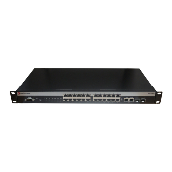
Hardware Components
The following figures show the several types of front panel port
and rear panel connections on A2 switches.
Figure 1
A2H123-24
Figure 2
A2H124-24, A2H124-24P
Figure 3
A2H124-24FX
Figure 4
A2H124-48, A2H124-48P
Figure 5
A2H254-16
Figure 6
A2 Switch Rear (A2H124-24 Displayed)
Key
DB9 RS232 console port connector
1
2
Password Reset button
3
Switch Status LEDs
4
RJ45 10/100 Mbps ports
5
MT-RJ fiber-optic ports
SFP slots
6
7
LC connector, 100BASE-FX connections
8
RJ45 ports for stack connections
9
RJ45 port status LEDs
MT-RJ port status LEDs
10
11
SFP port status LEDs
12
LC connector, 100BASE-FX status LEDs
13
RJ45 stack port status LEDs
Redundant power supply (RPS) DC connector
14
15
AC power input connector
Handling the Switch
™
A2
Caution: The switch can be damaged by electrostatic
discharge.
To prevent electrostatic damage, attach an electrostatic discharge
(ESD) wrist strap to your wrist before handling the switch.
Unpacking the Switch
Unpack the switch as follows:
1. Remove the packing material protecting the switch.
2. Remove the switch from the non‐conductive bag.
3. Perform a visual inspection of the switch for any signs of
physical damage. Contact Enterasys Networks if there are any
signs of damage. See "Getting Help" for more information on
contacting Enterasys Networks.
Connecting Power to the Switch
Note: Enterasys Networks recommends installing
any components before powering on your switch.
You can connect an A2 switch to a single, primary source of power,
or to two sources of power for redundancy.
The following redundant power supplies are available for purchase
from Enterasys Networks for connection to an A2 switch:
• C2RPS‐PSM, a 150 watt DC power supply capable of providing
power to a fully‐loaded non‐PoE switch.
• C2RPS‐POE (A2H124‐24P and A2H124‐48P only), 500 watt DC
power supply for PoE switches.
To power‐up your A2 switch:
1. If you are connecting a redundant power supply, attach the
C2RPS‐PSM cable (for non PoE) or C2RPS‐POE cable (for PoE)
from your redundant power supply to the A2 switch's
redundant power connector.
2. Attach the AC power cord to the A2 switch's AC input power
connector.
3. Plug the redundant power supply (if applicable) and the A2
switch AC power cords into dedicated, grounded AC outlets.
Note: To take full advantage of redundancy, each power
supply should be plugged-in to a separate, dedicated AC
outlet.
4. Once power is connected, verify that the RPS power LED turns
green, and the CPU (system) LED turns amber until the A2
switch finishes its initialization.
5. If the initialization process is successful, the CPU LED turns
green. If the CPU LED does not turn green, refer to the
SecureStack A2 Hardware Installation Guide associated with your
A2 switch for troubleshooting information.
Completing the Setup and Downloading the Latest
Firmware
Once you have connected power to the A2 switch and verified LED
activity, you can complete the setup process as follows. Refer to the
SecureStack A2 Hardware Installation Guide associated with your A2
switch for more information.
1. Determine the latest A2 firmware version by visiting the
Enterasys Networks download site at:
http://secure.enterasys.com/services/support/downloads/software
2. Connect the switch to the network.
3. Connect a management station to the console port.
4. Verify that the network devices connected to the switch ports
are powered on, and that each link/activity LED is on (solid
green or blinking green).
5. At the device connected to the console port, perform the
following:
a. Enter admin for Username.
b. At the Password prompt, press ENTER (RETURN).
c. At the command prompt, determine if the latest firmware
image is loaded on the switch by entering this command:
show version
d. If the output (under FW Version) displays an older version
number than that determined in Step 1, download and
activate the new version as directed on the download website.
(Alternatively, you can use the CLI command listed in
Table
1.)
Basic Setup Commands
Table
1 lists CLI commands that are required for setting up the A2
switch with the latest firmware. Table
2 lists additional basic
configurations for your A2 switch. For the complete list of CLI
commands, see the Enterasys SecureStack A2 Configuration Guide.
Table 1 Required CLI Setup Commands
Step Task
CLI commands
1
Set a new password
set password [username]
2
Set the switch IP address
set ip address ip-address [mask
ip-mask] [gateway ip-gateway]
3
Download, activate, and
copy
tftp://tftp_server_ip_address/
verify new firmware on the
filename system:image
switch using TFTP copy.
set boot system filename
Note: You can reboot the
show version
system immediately with the
set boot system command,
or reboot later with the reset
command.
Table 2 Optional CLI Setup Commands
Task
CLI commands
Save the active configuration
save config
Enable or disable SSH
set ssh enable | disable
Enable or disable Telnet
set telnet {enable | disable}
[inbound | outbound | all]
Enable or disable HTTP
set webview {enable | disable}
management (WebView)
Enable or disable SNMP port link
set port trap port-string
{enable | disable}
traps
Set the per port broadcast limit
set port broadcast port-string
threshold-value
Configure a VLAN
set vlan create vlan-id
set port vlan port-string
vlan-id modify-egress
Set a Syslog server IP and severity
set logging server index ip-addr
ip-addr severity severity state
enable
Configure and enable a RADIUS
set radius server index ip-addr
port [secret-value]{realm
server.
{management-access | any |
network-access}
set radius enable
Specifications
For a complete list of specifications, see the SecureStack A2
Hardware Installation Guide associated with your A2 switch.
Interfaces
Note: The 10/100BASE-T RJ45 ports on the A2H124-24P
and A2H124-48P also support 802.3af PoE connections.
A2H123‐24
• Twenty‐four 10/100BASE‐T RJ45 ports
• Two 100BASE‐FX fiber‐optic connections
• Two 10/100/1000BASE‐TX RJ45 connectors for stacking
A2H124‐24, A2H124‐24P
• Twenty‐four 10/100BASE‐T RJ45 ports
• Two gigabit SFP slots
• Two 10/100/1000BASE‐TX RJ45 connectors for stacking
A2H124‐24FX
• Twenty‐four 100BASE‐FX compliant ports
• Two gigabit SFP slots
• Two 10/100/1000BASE‐TX RJ45 connectors for stacking
A2H124‐48, A2H124‐48P
• Forty‐eight 10/100BASE‐T RJ45 ports
• Two gigabit SFP slots
• Two 10/100/1000BASE‐TX RJ45 connectors for stacking
A2H254‐16
• Eight 10/100BASE‐T RJ45 ports
• Eight 100BASE‐FX compliant ports
• Two gigabit SFP slots
• Two 10/100/1000BASE‐TX RJ45 connectors for stacking
Switch Dimensions
Size: 354.40 x 441 x 44.0 mm
Power Consumption
Input Voltage: 100 to 240VAC
Input Current:
• A2H124‐24P: 5.1 A Max
• A2H124‐48P: 5.0 A Max
• A2H123‐24, A2H124‐24, A2H124‐24FX: 1 A Max
• A2H254‐16: 0.5, 0.47
Temperature and Humidity
Operating: 0ºC to 50ºC
Storage: ‐40ºC to +70ºC
Operating relative humidity: 5% to 95%
Advertisement
Table of Contents

Related Manuals for Enterasys SecureStack A2 A2H124-24


Summary of Contents for Enterasys SecureStack A2 A2H124-24
- Page 1 Table 1 Required CLI Setup Commands Step Task Note: Enterasys Networks recommends installing Set a new password any components before powering on your switch. Set the switch IP address Download, activate, and verify new firmware on the switch using TFTP copy.
- Page 2 Klasse A ITE Anmerkung This table shows where these substances may be found in the supply chain of Enterasys’ electronic WARNHINWEIS: Dieses Produkt zählt zur Klasse A ( Industriebereich ). In Wohnbereichen kann information products, as of the date of sale of the enclosed product. Note that some of the component types es hierdurch zu Funkstörungen kommen, daher sollten angemessene Vorkehrungen zum Schutz ...
Need help?
Do you have a question about the SecureStack A2 A2H124-24 and is the answer not in the manual?
Questions and answers