Sign In
Upload
Download
Table of Contents
Contents
Add to my manuals
Delete from my manuals
Share
URL of this page:
HTML Link:
Bookmark this page
Add
Manual will be automatically added to "My Manuals"
Print this page
×
Bookmark added
×
Added to my manuals
Manuals
Brands
Enterasys Manuals
Switch
A4H124-24FX
Hardware installation manual
Enterasys A4H124-24FX Hardware Installation Manual
Fast ethernet switch
Hide thumbs
1
2
3
4
5
6
7
8
9
10
11
12
Table Of Contents
13
14
15
16
17
18
19
20
21
22
23
24
25
26
27
28
29
30
31
32
33
34
35
36
37
38
39
40
41
42
43
44
45
46
47
48
49
50
51
52
53
54
55
56
57
58
59
60
61
62
63
64
65
66
page
of
66
Go
/
66
Contents
Table of Contents
Troubleshooting
Bookmarks
Table of Contents
Table of Contents
About this Guide
Who Should Use this Guide
How to Use this Guide
Related Documents
Conventions Used in this Guide
Power Supply Replacement Part Numbers
Getting Help
For Information about
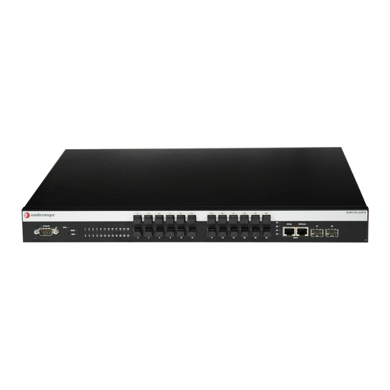
A4H124-24FX Front Panel
A4H254-8F8T Front Panel
A4 Switch Back Panel
Features
Management
Redundant Power Supply Capability
Stack Connections
Standards Compatibility
Switch Configuration Using CLI Commands
Switch Configuration Using Webview
Chapter 1: Introduction
Overview
A4 Switch Port Types
Chapter 2 : Installation
Considerations Prior to Installation
Required Tools
Unpacking the Switch
Installing the Switch on a Flat Surface
Installing the Rubber Feet
Guidelines for Flat Surface Installation
Rack Mounting the Switch
Area Guidelines for Switch Installation on Flat Surface
Guidelines for Rackmount Installation
Attaching the Brackets and Installing in a Rack
Attaching the Rackmount Brackets
Connecting Stacking Cables
Fastening the Switch to the Rack
High-Speed Stacking Cable Connections
Configuring Switches in a Stack
About A4 Switch Operation in a Stack
Installing a New Stackable System of up to Eight Switches
Recommended Procedures for New and Existing Stacks
Stack Manager Selection
Adding a New Switch to an Existing Stack
Connecting AC Power
Installing and Connecting a Redundant Power System
Stk-Rps-150Ps
Switch Rear View
Required Tools
Unpacking the Shelf and Power Supply
Installing an STK-RPS-150PS into a Shelf
Contents of STK-RPS-150CH2 Carton
Contents of STK-RPS-150CH8 Carton
Contents of STK-RPS-150PS Carton
STK-RPS-150PS Installation in an STK-RPS-150CH2 Shelf
Removing an Installed STK-RPS-150PS
STK-RPS-150PS Installation in an STK-RPS-150CH8 Shelf
Installing the Shelf into the Rack
Fastening the STK-RPS-150CH2 to the Rack
Connecting the RPS Cable and AC Power Cord
Fastening the STK-RPS-150CH8 to the Rack
Power Connectors on STK-RPS-150PS (Rear View)
STK-RPS-150PS RPS Cable and AC Power Cord Connections
Connecting to the Console Port for Local Management
What Is Needed
DB9 Male Console Port Pinout Assignments
Connecting to a PC
Connecting to a VT Series Terminal
Connecting to a Modem
Connecting to the Network
Connecting UTP Cables to RJ45 Ports
Connecting a UTP Cable Segment to an RJ45 Port
Preparing to Install an Optional SFP Transceiver
Installing an Optional SFP Transceiver
Installing an SFP Transceiver with RJ45 Connector
Installing an SFP Transceiver with MT-RJ Connector
Removing an SFP Transceiver
Installing an SFP Transceiver with an LC Connector
Connecting Fiber-Optic Cables to Fixed MT-RJ Ports
Connecting Fiber-Optic Cables to SFP Ports
Connecting a Fiber-Optic Cable Segment to Fixed MT-RJ Port
Completing the Installation
Initial Logon to Switch Management
Chapter 3: Troubleshooting
Checking the Leds
Mgr Led
MGR LED Definitions
A4 Chassis Leds (A4H254-8F8T Shown)
Rps Led
Up Led
RPS LED Definitions
UP LED Definitions
Cpu Led
Down Led
DOWN LED Definitions
CPU LED Definitions
Link/Activity Leds
Port LED Definitions
Troubleshooting Checklist
Using the Password Reset Button
Removing the Switch from a Rack
Appendix A: Specifications
Switch Specifications
A4 Switch Specifications
Fixed MT-RJ Port Specifications
Fixed MT-RJ Port Specifications
Redundant Power Supply Specifications
STK-RPS-150CH2 Chassis Specifications
STK-RPS-150CH8 Chassis Specifications
STK-RPS-150CH2 Specifications
STK-RPS-150CH8 Specifications
STK-RPS-150PS Specifications
STK-RPS-150PS Redundant Power Supply Connector
STK-RPS-150PS Power Supply Connector Pin Locations
Torque Values
Pluggable Transceiver Specifications
Console Port Pinout Assignments
Regulatory Compliance
STK-RPS-150CH2 Power Supply Connector Pin Functions
Recommended Torque Values by Screw Size
Compliance Standards
Advertisement
Quick Links
1
A4 Switch Port Types
2
A4H124-24Fx Front Panel
3
Switch Configuration Using Cli Commands
4
Connecting to a Pc
Download this manual
Enterasys
®
Fast Ethernet Switch
Hardware Installation Guide
A4H124-24FX
A4H254-8F8T
P/N 9034608-03
A4
Table of
Contents
Previous
Page
Next
Page
1
2
3
4
5
Advertisement
Table of Contents
Troubleshooting
Chapter 3: Troubleshooting
53
Troubleshooting Checklist
58
Need help?
Do you have a question about the A4H124-24FX and is the answer not in the manual?
Ask a question
Questions and answers
Related Manuals for Enterasys A4H124-24FX
Switch Enterasys SecureStack A2 A2H124-24 Quick Reference
Enterasys securestack a2 a2h124-24: quick start (2 pages)
Switch Enterasys SecureStack A2 A2H124-24 Datasheet
A-series fast ethernet stackable l2 switch (8 pages)
Switch Enterasys ENTERASYS ATX User Manual
Netsight element manager (82 pages)
Switch Enterasys SecureStack A2 A2H123-24 Hardware Installation Manual
Enterasys securestack a2 a2h123-24: install guide (64 pages)
Switch Enterasys Enterasys SecureStack A2 A2H254-16 Hardware Installation Manual
Enterasys networks fast ethernet switches hardware installation guide (80 pages)
Switch Enterasys A4H254-8F8T Hardware Installation Manual
Fast ethernet switch (66 pages)
Switch Enterasys A4H124-24 Hardware Installation Manual
Fast ethernet switch (68 pages)
Switch Enterasys A4H124-48 Hardware Installation Manual
Fast ethernet switch (68 pages)
Switch Enterasys A4H124-48P Hardware Installation Manual
Fast ethernet switch (68 pages)
Switch Enterasys Enterasys Gold Distributed Forwarding Engine 4G4282-49 Hardware Installation Manual
Enterasys networks switch hardware installation guide (90 pages)
Switch Enterasys Enterasys 6H308-48 Hardware Installation Manual
Dfe‐gold series module (90 pages)
Switch Enterasys Enterasys Gold Distributed Forwarding Engine 4H4202-72 Hardware Installation Manual
Enterasys networks switch hardware installation guide (90 pages)
Switch Enterasys Enterasys Matrix DFE-Gold Series Configuration Manual
Enterasys networks switch configuration guide (944 pages)
Switch Enterasys Enterasys Vertical Horizon VH-2402S Release Notes
Vertical horizon 24-port 10/100 ethernet switch (8 pages)
Switch Enterasys Enterasys SecureStack B2 B2G124-24 Hardware Installation Manual
Gigabit and fast ethernet switches (80 pages)
Switch Enterasys Matrix-V V2H124-24FX Hardware Installation Manual
Matrix v-series fast ethernet switch (74 pages)
This manual is also suitable for:
A4h254-8f8t
Table of Contents
Print
Rename the bookmark
Delete bookmark?
Delete from my manuals?
Login
Sign In
OR
Sign in with Facebook
Sign in with Google
Upload manual
Upload from disk
Upload from URL


Need help?
Do you have a question about the A4H124-24FX and is the answer not in the manual?
Questions and answers