DV Systems G20 Maintenance And Service Data
Rotary screw air compressor units
Hide thumbs
Also See for G20:
- Installation and start-up manual (37 pages) ,
- Installation and start-up data (38 pages)
Table of Contents
Advertisement
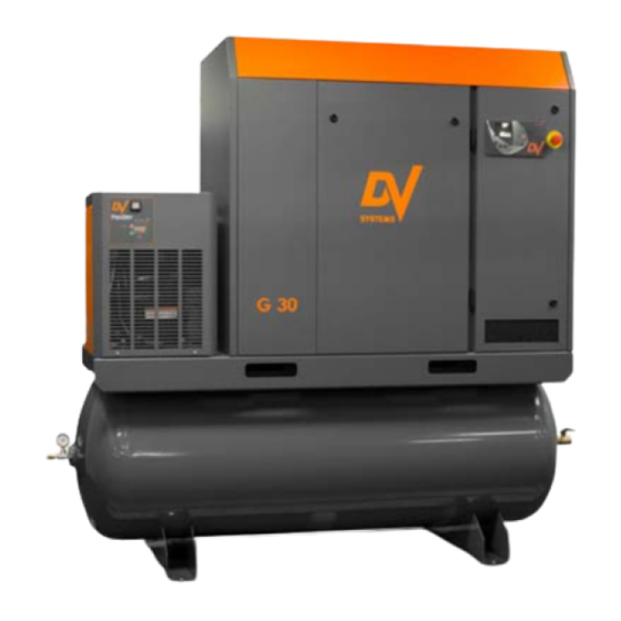
G20 (T) (TD),
G25 (T) (TD) &
G30 (T) (TD)
Rotary Screw
Air Compressor
Units
- - -
Maintenance
And
Service Data
If you require assistance, please contact your local DV Systems Distributor or Authorized Service
center. You may contact the manufacturer directly as follows:
Contents:
Safety Precautions ..........................................
Unit Operation .................................................
Lubrication ....................................................
AC Motor Maintenance Instructions ........................ 5
Start-up Procedures ........................................
Preventative Maintenance Schedule ...................
Maintenance Procedures ...................................
CSC300 Controller ...........................................
Common Compressor Faults .............................
Variable Speed Drive ......................................
Separator Filter & Refrigerated Air Dryer .............
Trouble-Shooting Guide ....................................
Warranty ........................................................
Please read this manual before
safe place for future reference.
procedures in this reference manual apply
Phone: (705) 728-5657
Web: www.dvsystems.com
Email: sales@dvsystems.com
- 1 -
installing or using your Air
Compressor Unit. It contains
valuable information that will
help in the receiving,
installation, use, and
maintenance of the Unit.
Please keep this manual in a
All of the information, policies, and
exclusively to DV Systems.
G2030-II-S
Apr '19
Page:
2
3
4
6
7
9
14
23
24
29
32
35
Advertisement
Table of Contents

Related Manuals for DV Systems G20


Summary of Contents for DV Systems G20
- Page 1 All of the information, policies, and procedures in this reference manual apply exclusively to DV Systems. If you require assistance, please contact your local DV Systems Distributor or Authorized Service center. You may contact the manufacturer directly as follows: Phone: (705) 728-5657 Web: www.dvsystems.com...
-
Page 2: Safety Precautions
G2030-II-S Apr ‘19 Safety Precautions In order to operate the Compressor Unit safely and correctly, we have opted to use the following symbols to make you aware of important points. These points relate to user safety and preventing equipment problems. Please pay close attention to these sections. -
Page 3: Unit Operation
G2030-II-S Apr ‘19 Unit Operation Shown below is the ‘CSC300’ Controller which regulates the operation of the Unit. It is used to start and stop the Unit, and it provides information as to system pressure, temperature, etc. Starting the Unit: Press the ‘Start’... -
Page 4: Initial Start-Up
Reservoir with new oil using only the DV (1) Scavenge Line Tube (‘DSC-382’) Systems ‘DEV-3000’ oil. The ‘MK-G20-30-1’ Kit is appropriate for Units of serial number ‘37162’ and higher. Use ‘MK-G20-30’ Kit for Units of serial number ‘37135’ and lower. -
Page 5: Ac Motor Maintenance Instructions
G2030-II-S Apr ‘19 AC Motor Maintenance Instructions Cleaning. To ensure that the Motor operates at optimum temperatures and provides years of trouble-free service, periodically clean the outside of the Motor Housing of any build-up of dust, etc. Though it is not anticipated that, if installed correctly and in a suitable environment, there should be much build-up on the Motor, keeping the Housing clean will allow the Motor to operate more efficiently. -
Page 6: Start-Up Procedures
G2030-II-S Apr ‘19 Start-up Procedures Do not attempt to operate the Unit without first checking whether there is oil in the Oil Reservoir. Add oil as required. Serious damage may result from use, however limited, without oil. 3) Place the Fused Disconnect / Breaker in the ‘On’ Unit Controls Position. -
Page 7: Preventative Maintenance Schedule
Noted on the following pages are general Maintenance guidelines based on average working conditions. Should the Unit be worked under extreme conditions, please contact your DV Systems Distributor for further input. As well, all maintenance/service work must be carried out by a qualified Technician. - Page 8 ‘#’ must be changed twice as often (example: in 4000 hours instead of 8000), and not as noted above. b) The DV Systems Oil used in the Rotary Screw Units is rated as an 8000 hour Oil. A complete Oil change must be done every 8000 hours of Unit operation, or every 12 months, whichever occurs first.
-
Page 9: Maintenance Procedures
2) Remove the Air Filter Element from the Unit. 3) Clean the Intake Valve area of any dust or build-up. 4) Install a new Air Filter (DV Systems Part Number ‘DSC-001961’), ensure it fits snugly on the Intake Valve Assembly, and tighten the Filter Clamp. -
Page 10: Cleaning The Heat Exchanger
Fill the Oil Reservoir to the centre of the Sight Glass as shown below. Do not under or overfill. Use only DV Systems ‘DEV-3000’ Synthetic Oil available in both 1 US Oil Fill Port gallon (3.8 litre) jugs or 5 US gallon (5 x 3.8 litre) pails. - Page 11 Hertz (New / Old)* Pound Force / Inch Deflection** 120 psig (8.3 bar) 64 / 56 11.0 lb / 0.51" G20 (TD) 11.0 lb / 0.52" 145 psig (10 bar) 62 / 55 11.0 lb / 0.51" 120 psig (8.3 bar)
- Page 12 G2030-II-S Apr ‘19 Maintenance Procedures (cont’d) Changing the Scavenge Line ‘In-Line’ Filter. The ‘DSC-612’ In-Line’ Filter is located in the Scavenge Line between the Air-Oil Separator and the Air End, and removes any particles from the oil before it enters the Air End.
- Page 13 G2030-II-S Apr ‘19 Maintenance Procedures (cont’d) Thermo Valve Repair Kit. Spring The Thermostatic Valve, or commonly called ‘Thermo Valve’, provides a means of re-directing the oil to be cooled. At start-up, the oil travels from the Oil Reservoir, through the Oil Filter, and into the Air End. End Cap As the oil temperature reaches approx.
-
Page 14: Description Of Controller
G2030-II-S Apr ‘19 ‘CSC300’ Controller Description of Controller. The ‘CSC300’ Controller is the ‘brains’ of the G series Rotary Screw Compressor Units. It monitors, enables, and indicates the various functions of the Unit. The Controller voltage requirement is 24 volts +/- 15%. The Controller is comprised of several levels of access, segregated into: - Operator Level (Access Code: ‘2012’) - indicates the main operating parameters (eg, temperature, pressure, etc) and faults of the unit. - Page 15 Unit. Any adjustments made to the above parameters by others (other than a qualified Technician) resulting in the incorrect operation of the Unit, damage to the Unit, or damage to property is not covered by the DV Systems Warranty.
-
Page 16: Controller Structure
G2030-II-S Apr ‘19 ‘CSC300’ Controller (cont’d) Controller Structure. The chart below indicates the various fields of the ‘CSC300’ Controller, some require an Access Code. As suggested on the previous page, only those qualified should be permitted to make any adjustments to the parameters. - Page 17 G2030-II-S Apr ‘19 ‘CSC300’ Controller (cont’d) Page ‘P21’ – Run schedule Page ‘P80’ – ISC main menu Page ‘P81’ – ISC settings 01 Run schedule (Shown if active) (Shown if active) 02 Workday edit 01 ISC enabled 01 ISC # compressors 03 Schedule entry 02 Offload pressure 02 ISC start delay...
- Page 18 G2030-II-S Apr ‘19 ‘CSC300’ Controller (cont’d) Adjusting the parameters of the Controller could adversely affect the operation of the Unit. Only those individuals with knowledge of the Unit should be permitted to make any adjustments. Access Code Entry. To gain entry to areas of the Controller in which an Access Code is required: 1.
- Page 19 G2030-II-S Apr ‘19 ‘CSC300’ Controller (cont’d) 9. Using the ‘Up’ and ‘Down’ keys, change 10. Press ‘Enter’ to move to the following the first digit of the Access Code to the digit. Using the ‘Up’, ‘Down’, and ‘Enter’ appropriate number keys, input the access code.
-
Page 20: Page Menus
G2030-II-S Apr ‘19 ‘CSC300’ Controller (cont’d) Page Menus. Once the correct Access Code has been entered, access will be given to pages reflecting that Code. Refer to Page 18 and 19 for available pages. Use ‘Enter’ and ‘Escape’ keys on the Controller to navigate between menu page navigation and menu content navigation. -
Page 21: Error Log Menu
G2030-II-S Apr ‘19 ‘CSC300’ Controller (cont’d) Error Log Menu. Any issues that the Unit may have are stored on an Error Log. It places in its memory the last 50 faults in chronological order. If all 50 faults have been used, any new faults will become ‘01’, and all others will be moved back one step. - Page 22 G2030-II-S Apr ‘19 ‘CSC300’ Controller (cont’d) Advanced Phase Detection Advanced Phase Detection feature of the CSC300 controller is utilized in fixed speed units. It measures the phase sequence of the incoming power to prevent motor from rotating in the wrong direction. If the following error is visible on the Screen and the Unit will not start, simply switch power leads L1 and L3.
-
Page 23: Common Compressor Faults
G2030-II-S Apr ‘19 Common Compressor Faults Common Faults. Noted below are the most common Faults experienced. ‘CSC300’ Alarms. There is an issue with the Unit, but it will still operate. Code: Description: Most Common Items to Check: A:0083 Motor phase imbalance Check supply voltage, fuses and cable Solenoid not working, Intake Valve Orifice clogged, Transducer dirty or faulty, pressure changed A:0119... -
Page 24: Variable Speed Drive
Apr ‘19 Variable Speed Drive Your DV Systems ‘G Series’ Rotary Screw Compressor Unit may have been equipped with a Vacon ‘Variable Speed Drive’, or ‘VSD’. A Compressor with an integral VSD can handle the constant loads for an extended period of time (running at close to 100% duty cycle), but it can also run at slower speeds to accommodate lower air demands at other times of the day. - Page 25 G2030-II-S Apr ‘19 Variable Speed Drive (cont’d) Operating Screen Status Fields Control Place Location Field Status LED Typical Drive Status Indicators on Screen The Status LED of the drive shows the status of the drive. It can show 5 different statuses. Color of the LED light Status of the drive Blinking slowly...
- Page 26 G2030-II-S Apr ‘19 Variable Speed Drive (cont’d) Keypad Buttons Back/Reset Button Move back in the menu, exit the Edit mode, reset a fault. Arrow UP Scroll the menu up and to increase a value. FUNCT button Not Used. Arrow RIGHT Scroll right.
- Page 27 G2030-II-S Apr ‘19 Variable Speed Drive (cont’d) Menu Structure - 27 -...
- Page 28 G2030-II-S Apr ‘19 Variable Speed Drive (cont’d) Common VSD Fault Codes Noted below are the most common fault codes that may appear on the VSD. For a more thorough list, please check the manual which deals exclusively with the Vacon Variable Speed Drive and which accompanied the Unit. Fault Fault Possible Causes:...
- Page 29 G2030-II-S Apr ‘19 Separator Filter and Refrigerated Air Dryer Your Unit may be equipped with a Separator Filter and an ‘ASD Series’ Refrigerated Air Dryer Unit as indicated below. These items are located in the compressed air lines after the air is compressed but before it enters the Air Receiver.
- Page 30 G2030-II-S Apr ‘19 Separator Filter and Refrigerated Air Dryer (cont’d) Motors. Typical Dryer Operation. The Dryer will operate as follows: Pressing the ‘On/Off’ Button for 3 seconds will start the Unit • There is a time delay of up to 2 minutes before the Refrigerant Compressor starts. •...
-
Page 31: Filter Element Replacement
G2030-II-S Apr ‘19 Separator Filter and Refrigerated Air Dryer (cont’d) Typical Separator Filter. As previously noted, the Separator Filter is located between the Air End and the Refrigerated Dryer. It contains a 1 micron Separator Element which protects the Dryer Unit by removing liquids and solid particles 1 micron and larger. -
Page 32: Troubleshooting Guide
Compressor Unit unless you are familiar with it, as there are many issues that may come into play, the most important being personal safety and the welfare of the Unit. Should you have any questions, or require servicing to your Unit, please contact your local DV Systems Distributor/Service Center. - Page 33 G2030-II-S Apr ‘19 Trouble Shooting Guide (cont’d) Condition: Cause: Suggested Correction: B. No or Insufficient Air Flow. Air Filter is dirty. Replace the Air Filter. Oil Separator is blocked. Replace the Oil Separator. Intake Valve is faulty. Repair or replace the Intake Valve. Air leaks in the system.
- Page 34 G2030-II-S Apr ‘19 Trouble Shooting Guide (cont’d) Condition: Cause: Suggested Correction: E. Intake Valve Leaks Oil Intake Valve Seal leaks. Repair using an Intake Valve Repair Kit. When Unit Stops. Intake Valve stuck in open position. Repair or replace the Intake Valve. Blowdown Solenoid not functioning.
- Page 35 Oil changes must be done more frequently. B) Oil Filter must be changed every 4000 hours (not to exceed 6 months) from the date of initial start-up using the appropriate DV Systems part. When operating in adverse conditions, Oil Filter changes must be done more frequently.
Need help?
Do you have a question about the G20 and is the answer not in the manual?
Questions and answers