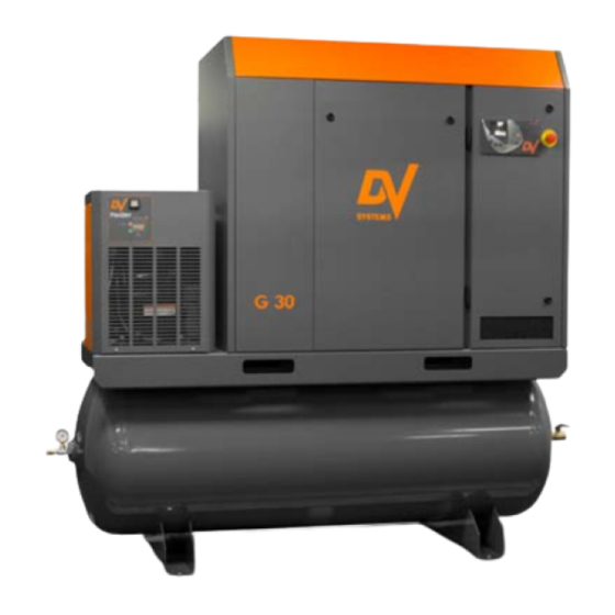
DV Systems G20 Installation And Start-Up Data
Rotary screw
air compressor
units
Hide thumbs
Also See for G20:
- Installation and start-up manual (37 pages) ,
- Maintenance and service data (36 pages)
Table of Contents
Advertisement
G20 (T) (TD),
G25 (T) (TD) &
G30 (T) (TD)
Rotary Screw
Air Compressor
Units
- - -
Installation
And
Start-up Data
If you require assistance, please contact your local DV Systems Distributor or Authorized Service
center. You may contact the manufacturer directly as follows:
Phone:
(705) 728-5657 (Canada)
(704) 799-0046 (USA)
Fax:
(705) 728-4974 (Canada)
(704) 799-0355 (USA)
Contents:
Quick Start ............................................................
Safety Precautions ..........................................
Unpacking and Inspection .................................
Installation – Mechanical ..................................
Lubrication ....................................................
Installation – Electrical .....................................
Start-up Procedures ........................................
Preventative Maintenance Schedule ...................
Common Compressor Faults .............................
Variable Speed Drive ......................................
Separator Filter & Refrigerated Air Dryer .............
Trouble-Shooting Guide ....................................
Warranty ........................................................
Please read this manual before
installing or using your Air
Compressor Unit. It contains
valuable information that will
help in the receiving,
installation, use, and
maintenance of the Unit.
Please keep this manual in a
safe place for future reference.
All of the information, policies, and
procedures in this reference manual apply
Web:
www.dvcompressors.com
Email:
sales@dvcompressors.com (Canada)
orders@dvcompressors.com (USA)
- 1 -
exclusively to DV Systems.
G2030-II-C
Mar '17
Page:
2
5
6
7
10
11
14
15
17
18
21
24
27
Advertisement
Table of Contents

Related Manuals for DV Systems G20


Summary of Contents for DV Systems G20
- Page 1 All of the information, policies, and procedures in this reference manual apply exclusively to DV Systems. If you require assistance, please contact your local DV Systems Distributor or Authorized Service center. You may contact the manufacturer directly as follows: Phone:...
-
Page 2: Quick Start
G2030-II-C Mar ‘17 Quick Start Mechanical Installation. (Refer to Page 6) The Unit should be located in a dry, clean, cool, dust free, and well ventilated area. Allow a minimum 18” (458mm) around and 36” (915mm) above Unit. ... - Page 3 G2030-II-C Mar ‘17 Quick Start (cont’d) Shipping Cleats. (1) Cleat at Motor Mount The ‘G Series’ Screw Units are shipped with (3) Shipping Cleats that must be removed prior to operating the Unit. (2) Cleats are located under the Belt / Pulley Housing as shown at right.
-
Page 4: Unit Operation
G2030-II-C Mar ‘17 Quick Start (cont’d) Unit Operation. Shown below is the ‘CSC300’ Controller which regulates the operation of the Unit. It is used to start and stop the Unit, and it provides information as to system pressure, temperature, etc. Starting the Unit: Press the ‘Start’... -
Page 5: Safety Precautions
G2030-II-C Mar ‘17 Safety Precautions In order to operate the Compressor Unit safely and correctly, we have opted to use the following symbols to make you aware of important points. These points relate to user safety and preventing equipment problems. Please pay close attention to these sections. -
Page 6: Unpacking And Inspection
Shipments of DV Systems products are the property of the Consignee when the products leave our facility. DV Systems Inc. is not responsible for any damages or shortages caused to the product after it has left our shipping dock. -
Page 7: Installation - Mechanical
G2030-II-C Mar ‘17 Installation – Mechanical Moving of the Unit. When moving the Air Compressor, the forklift or hand lift forks go under the Unit from the directions as indicated. When lifting from position ‘A’, use extended forks. Please be advised that care must be taken when moving and positioning the Units as they are top heavy. - Page 8 G2030-II-C Mar ‘17 Installation – Mechanical (cont’d) Shown below and on the following page are items which assist in making a good installation. These are both intake and exhaust ductwork, helping the Unit to a) draw in clean outside air and b) exhaust the warmer air away from the Unit.
- Page 9 G2030-II-C Mar ‘17 Installation – Mechanical (cont’d) Intake and Exhaust Ducting – Tank Mounted Unit - 9 -...
-
Page 10: Initial Start-Up
(1) In Line Filter (‘DSC-612) Reservoir with new oil using only the DV Systems ‘DEV-3000’ oil. The ‘MK-G20-30-1’ Kit is appropriate for Units of serial number ‘37162’ and higher. Use ‘MK-G20-30’ Kit for Units of serial number ‘37135’ and lower. -
Page 11: Installation - Electrical
Ensure that a suitable Fused Disconnect or Breaker through the Compressor Cabinet, and to the Switch (by others than DV Systems) is installed in the in the Compressor Control Panel, must be rated for electrical supply before the Compressor Unit. -
Page 12: Electrical Connection
Contact your local Distributor or Service Centre if additional information is needed. The Warranty that exists on the Electric Motor is that of the original manufacturer. In the event of a Motor failure, contact your DV Systems Distributor or Service Centre for the location of the nearest authorized Motor Service Centre. -
Page 13: Ac Motor Maintenance Instructions
G2030-II-C Mar ‘17 AC Motor Maintenance Instructions Cleaning. To ensure that the Motor operates at optimum temperatures and provides years of trouble-free service, periodically clean the outside of the Motor Housing of any build-up of dust, etc. Though it is not anticipated that, if installed correctly and in a suitable environment, there should be much build-up on the Motor, keeping the Housing clean will allow the Motor to operate more efficiently. -
Page 14: Start-Up Procedures
G2030-II-C Mar ‘17 Start-up Procedures Do not attempt to operate the Unit without first checking whether there is oil in the Oil Reservoir. Add oil as required. Serious damage may result from use, however limited, without oil. 3) Place the Fused Disconnect / Breaker in the ‘On’ Unit Controls Position. -
Page 15: Preventative Maintenance Schedule
Noted on the following pages are general Maintenance guidelines based on average working conditions. Should the Unit be worked under extreme conditions, please contact your DV Systems Distributor for further input. As well, all maintenance/service work must be carried out by a qualified Technician. - Page 16 ‘#’ must be changed twice as often (example: in 4000 hours instead of 8000), and not as noted above. b) The DV Systems Oil used in the Rotary Screw Units is rated as an 8000 hour Oil. A complete Oil change must be done every 8000 hours of Unit operation, or every 12 months, whichever occurs first.
-
Page 17: Common Compressor Faults
G2030-II-C Mar ‘17 Common Compressor Faults Common Faults. Noted below are the most common Faults experienced. ‘CSC300’ Alarms. There is an issue with the Unit, but it will still operate. Code: Description: Most Common Items to Check: A:0083 Motor phase imbalance Check supply voltage, fuses and cable Solenoid not working, Intake Valve Orifice clogged, Transducer dirty or faulty, pressure changed A:0119... -
Page 18: Variable Speed Drive
Mar ‘17 Variable Speed Drive Your DV Systems ‘G Series’ Rotary Screw Compressor Unit may have been equipped with an optional ‘Variable Speed Drive’, or ‘VSD’. A Compressor with an integral VSD can handle the constant loads for an extended period of time (running at close to 100% duty cycle), but it can also run at slower speeds to accommodate lower air demands at other times of the day. - Page 19 G2030-II-C Mar ‘17 Variable Speed Drive (cont’d) Operating Screen Status Fields Control Place Location Field Status LED Typical Drive Status Indicators The Status LED of the drive shows the status of the drive. It can show 5 different statuses. Color of the LED light Status of the drive Blinking slowly Ready...
- Page 20 G2030-II-C Mar ‘17 Variable Speed Drive (cont’d) Common VSD Fault Codes Noted below are the most common fault codes that may appear on the VSD. For a more thorough list, please check the manual which deals exclusively with the Vacon Variable Speed Drive and which accompanied the Unit. Fault Fault Possible Causes:...
- Page 21 G2030-II-C Mar ‘17 Separator Filter and Refrigerated Air Dryer Your Unit may be equipped with a Separator Filter and an ‘ASD Series’ Refrigerated Air Dryer Unit as indicated below. These items are located in the compressed air lines after the air is compressed but before it enters the Air Receiver.
- Page 22 G2030-II-C Mar ‘17 Separator Filter and Refrigerated Air Dryer (cont’d) Motors. Typical Dryer Operation. The Dryer will operate as follows: Pressing the ‘On/Off’ Button for 3 seconds will start the Unit There is a time delay of up to 2 minutes before the Refrigerant Compressor starts. ...
-
Page 23: Filter Element Replacement
G2030-II-C Mar ‘17 Separator Filter and Refrigerated Air Dryer (cont’d) Typical Separator Filter. As previously noted, the Separator Filter is located between the Air End and the Refrigerated Dryer. It contains a 1 micron Separator Element which protects the Dryer Unit by removing liquids and solid particles 1 microns and larger. -
Page 24: Troubleshooting Guide
Compressor Unit unless you are familiar with it, as there are many issues that may come into play, the most important being personal safety and the welfare of the Unit. Should you have any questions, or require servicing to your Unit, please contact your local DV Systems Distributor/Service Center. - Page 25 G2030-II-C Mar ‘17 Trouble Shooting Guide (cont’d) Condition: Cause: Suggested Correction: B. No or Insufficient Air Flow. Air Filter is dirty. Replace the Air Filter. Oil Separator is blocked. Replace the Oil Separator. Intake Valve is faulty. Repair or replace the Intake Valve. Air leaks in the system.
- Page 26 G2030-II-C Mar ‘17 Trouble Shooting Guide (cont’d) Condition: Cause: Suggested Correction: E. Intake Valve Leaks Oil Intake Valve Seal leaks. Repair using an Intake Valve Repair Kit. When Unit Stops. Intake Valve stuck in open position. Repair or replace the Intake Valve. Blowdown Solenoid not functioning.
- Page 27 Oil changes must be done more frequently. B) Oil Filter must be changed every 4000 hours (not to exceed 6 months) from the date of initial start-up using the appropriate DV Systems part. When operating in adverse conditions, Oil Filter changes must be done more frequently.
- Page 28 SALES-ENGINEERING DRAWING G20-30 SCREW COMPRESSOR or reproduced in any manner, nor submitted to other parties for examination without the prior approval of DV SYSTEMS, INC. DV SYSTEMS, INC. is continually trying to improve its products, DRAWING NO. SHT NO REV.
- Page 29 G20-30TD SCREW COMPRESSOR or reproduced in any manner, nor submitted to other parties for examination without the prior WITH DRYER approval of DV SYSTEMS, INC. DV SYSTEMS, INC. is continually trying to improve its products, DRAWING NO. SHT NO REV.
- Page 30 SALES-ENGINEERING DRAWING G25-30VSD SCREW COMPRESSOR or reproduced in any manner, nor submitted to other parties for examination without the prior approval of DV SYSTEMS, INC. DV SYSTEMS, INC. is continually trying to improve its products, DRAWING NO. SHT NO REV.
- Page 31 G25-30TDVSD SCREW COMPRESSOR or reproduced in any manner, nor submitted to other parties for examination without the prior WITH DRYER approval of DV SYSTEMS, INC. DV SYSTEMS, INC. is continually trying to improve its products, DRAWING NO. SHT NO REV.
- Page 32 CHECKED BY SCALE IMPORTANT NOTE: This print is the confidential property of DV SYSTEMS, INC. It is not to be used or reproduced G20-30II in any manner, nor submitted to other parties for examination without the prior approval of DV SYSTEMS, INC.
- Page 33 CHECKED BY SCALE IMPORTANT NOTE: This print is the confidential property of DV SYSTEMS, INC. It is not to be used or reproduced G20-30II in any manner, nor submitted to other parties for examination without the prior approval of DV SYSTEMS, INC.
- Page 34 CHECKED BY SCALE IMPORTANT NOTE: This print is the confidential property of DV SYSTEMS, INC. It is not to be used or reproduced G20-30II in any manner, nor submitted to other parties for examination without the prior approval of DV SYSTEMS, INC.
- Page 35 CURRENT SENSOR TRANSFORMER SECONDARY FUSES F3 IMPORTANT NOTE: This print is the confidential property of DV SYSTEMS, INC. ELECTRICAL SCHEMATICS It is not to be used or reproduced in any manner, nor submitted to other parties G-SERIES FIXED SPEED COMPRESSOR WITH MICROPROCESSOR for examination without the prior approval of DV SYSTEMS, INC.
- Page 36 WARNING: USE THE SAME FUSE TYPE & RATING WIRING WIRING POWER BLOCK IMPORTANT NOTE: This print is the confidential property of DV SYSTEMS, INC. ELECTRICAL SCHEMATICS It is not to be used or reproduced in any manner, nor submitted to other parties SCREW COMPRESSOR VARIABLE SPEED CSC300 &...
- Page 37 WARNING: USE THE SAME FUSE TYPE & RATING WIRING WIRING POWER BLOCK IMPORTANT NOTE: This print is the confidential property of DV SYSTEMS, INC. ELECTRICAL SCHEMATICS It is not to be used or reproduced in any manner, nor submitted to other parties SCREW COMPRESSOR VARIABLE SPEED CSC300 &...
Need help?
Do you have a question about the G20 and is the answer not in the manual?
Questions and answers