Table of Contents
Advertisement
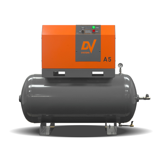
A5 (T)
Rotary Screw
Air Compressor
Units
- - -
Installation
And
Service Data
If you require assistance, please contact your local DV Systems Distributor or Authorized Service
center. You may contact the manufacturer directly as follows:
Phone:
(705) 728-5657 (Canada)
(704) 799-0046 (USA)
Fax:
(705) 728-4974 (Canada)
(704) 799-0355 (USA)
Contents:
Quick Start ............................................................
Safety Precautions ..........................................
Unpacking and Inspection .................................
Installation – Mechanical ..................................
Lubrication ....................................................
Installation – Electrical .....................................
Start-up Procedures ........................................
Preventative Maintenance Schedule ...................
Common Compressor Faults ..............................
Troubleshooting Guide ....................................
Warranty ........................................................
Please read this manual before
installing or using your Air
Compressor Unit. It contains
valuable information that will
help in the receiving,
installation, use, and
maintenance of the Unit.
Please keep this manual in a
safe place for future reference.
All of the information, policies, and
procedures in this reference manual apply
Web:
www.dvcompressors.com
Email:
sales@dvcompressors.com (Canada)
orders@dvcompressors.com (USA)
- 1 -
exclusively to DV Systems.
A5-C
Sep '15
Page:
2
4
5
6
8
9
11
12
14
15
18
Advertisement
Table of Contents

Related Manuals for DV Systems A5 (T)


Summary of Contents for DV Systems A5 (T)
- Page 1 All of the information, policies, and procedures in this reference manual apply exclusively to DV Systems. If you require assistance, please contact your local DV Systems Distributor or Authorized Service center. You may contact the manufacturer directly as follows: Phone:...
-
Page 2: Mechanical Installation
A5-C Sep ’15 Quick Start 36” [915mm] Mechanical Installation. (Refer to Page 6) 18” 18” [458mm] [458mm] 18” [458mm] Installation Kit IK515 Flex-Hose & Vibration Isolators The Unit should be located in a dry, clean, cool, (sold separately) dust free, and well ventilated area. Allow a minimum 18”... -
Page 3: Unit Operation
A5-C Sep ’15 Quick Start (cont’d) Unit Operation. Shown below is the ‘CSC15’ Controller which regulates the operation of the Unit. Unit Status LEDs, Hour Meter, and ON/OFF switch are located on the control panel cover. Starting the Unit: Turn the Selector Switch to ‘ON’ position. Stopping the Unit: Turn the Switch to ‘OFF’... -
Page 4: Safety Precautions
A5-C Sep ’15 Safety Precautions In order to operate the Compressor Unit safely and correctly, we have opted to use the following symbols to make you aware of important points. These points relate to user safety and preventing equipment problems. Please pay close attention to these sections. -
Page 5: Unpacking And Inspection
Shipments of DV Systems products are the property of the Consignee when the products leave our facility. DV Systems Inc. is not responsible for any damages or shortages caused to the product after it has left our shipping dock. -
Page 6: Installation - Mechanical
A5-C Sep ’15 Installation – Mechanical Moving of the Unit. When moving the Air Compressor, the forklift or hand lift forks go under the Unit from the directions as indicated. Please be advised that care must be taken when moving and positioning the Units as they are top heavy. - Page 7 A5-C Sep ’15 Installation – Mechanical (cont’d) Shown below are items which assist in making a good installation. These are both intake and exhaust ductwork, helping the Unit to a) draw in clean outside air and b) exhaust the warmer air away from the Unit. The warmer air may be used, with the inclusion of a damper in the exhaust ducting, to warm the interior of the building during the colder months of the year.
-
Page 8: Initial Start-Up
Oil level on a monthly basis. damage may result from use, however limited, without oil. Use only DV Systems ‘DEV-3000’ Synthetic Oil. Subsequent Oil Changes. Drain the existing oil from the Unit. (Please be advised that the Unit cannot be drained fully of oil, as some oil may remain in various components ie Cooler, Tubing, etc.) -
Page 9: Installation - Electrical
Ensure that a suitable Fused Disconnect or Breaker through the Compressor Cabinet, and to the Switch (by others than DV Systems) is installed in the in the Compressor Control Panel, must be rated for electrical supply before the Compressor Unit. -
Page 10: Electrical Connection
Contact your local Distributor or Service Centre if additional information is needed. The Warranty that exists on the Electric Motor is that of the original manufacturer. In the event of a Motor failure, contact your DV Systems Distributor or Service Centre for the location of the nearest authorized Motor Service Centre. -
Page 11: Start-Up Procedures
A5-C Sep ’15 Start-up Procedures Unit Controls Start/Stop Switch 6) Once the Unit reaches 145 psi (10bar), it will idle for 3 Start position: minutes and shut off. allows the Unit to start. 7) Open the Ball Valve slightly and allow the air to bleed Stop position: from the Tank. -
Page 12: Preventative Maintenance Schedule
Noted on the following pages are general Maintenance guidelines based on average working conditions. Should the Unit be worked under extreme conditions, please contact your DV Systems Distributor for further input. As well, all maintenance/service work must be carried out by a qualified Technician. - Page 13 A5-C Sep ’15 Preventative Maintenance Schedule (cont’d) Maintenance Interval (in 000’s of Hours) Maintenance Item: Daily Compressor Room Temperature Inspect Ambient Temperature should be between 10° C and 40° C (50° F and 104° F) Cleanliness Inspect Air Compressor Unit Check Oil Level Inspect Replace Oil...
-
Page 14: Common Compressor Faults
A5-C Sep ’15 Common Compressor Faults Common Faults. Noted below are the most common Faults experienced. ‘CSC15’ Alarms. There is an issue with the Unit, but it will still operate. Indication: Description: Most Common Items to Check: Service Due Service unit (please refer to Preventative Maintenance Schedule on pg. 13) [ Slow flash] ‘CSC15’... -
Page 15: Troubleshooting Guide
Compressor Unit unless you are familiar with it, as there are many issues that may come into play, the most important being personal safety and the welfare of the Unit. Should you have any questions, or require servicing to your Unit, please contact your local DV Systems Distributor/Service Center. - Page 16 A5-C Sep ’15 Trouble Shooting Guide (cont’d) Condition: Cause: Suggested Correction: B. No or Insufficient Air Flow. Air Filter is dirty. Replace the Air Filter. Oil Separator is blocked. Replace the Oil Separator. Intake Valve is faulty. Repair or replace the Intake Valve. Air leaks in the system.
- Page 17 A5-C Sep ’15 Trouble Shooting Guide (cont’d) Condition: Cause: Suggested Correction: F. Oil Consumption is Too Oil level is too high. Reduce the oil level to the proper level. High. Oil Return Line (Scavenge Line) is blocked. Clean and/or replace the Scavenge Line Sight Glass.
- Page 18 Oil changes must be done more frequently. B) Oil Filter must be changed every 4000 hours (not to exceed 12 months) from the date of initial start-up using the appropriate DV Systems part. When operating in adverse conditions, Oil Filter changes must be done more frequently.
Need help?
Do you have a question about the A5 (T) and is the answer not in the manual?
Questions and answers