Table of Contents
Advertisement
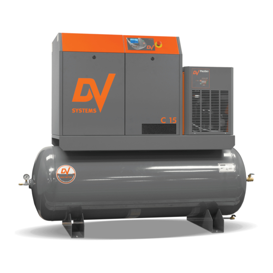
C10 (T) (TD)
C15 (T) (TD)
C15VSD (T) (TD)
Rotary Screw
Air Compressor
Units
- - -
Installation
And
Start-up Data
If you require assistance, please contact your local DV Systems Distributor or Authorized Service
center. You may contact the manufacturer directly as follows:
Contents:
Quick Start ............................................................
Safety Precautions ..........................................
Unpacking and Inspection .................................
Installation – Mechanical ..................................
Lubrication ....................................................
Installation – Electrical .....................................
Start-up Procedures ........................................
Preventative Maintenance Schedule ...................
Common Compressor Faults .............................
Separator Filter & Refrigerated Air Dryer .............
Trouble-Shooting Guide ....................................
Warranty ........................................................
Please read this manual before
safe place for future reference.
procedures in this reference manual apply
Phone: (705) 728-5657
Web: www.dvsystems.com
Email: sales@dvsystems.com
- 1 -
installing or using your Air
Compressor Unit. It contains
valuable information that will
help in the receiving,
installation, use, and
maintenance of the Unit.
Please keep this manual in a
All of the information, policies, and
exclusively to DV Systems.
C1015-II-C
Jun '21
Page:
2
4
5
6
8
9
12
13
15
19
22
25
Advertisement
Table of Contents

Related Manuals for DV Systems C10


Summary of Contents for DV Systems C10
- Page 1 All of the information, policies, and procedures in this reference manual apply exclusively to DV Systems. If you require assistance, please contact your local DV Systems Distributor or Authorized Service center. You may contact the manufacturer directly as follows: Phone: (705) 728-5657 Web: www.dvsystems.com...
-
Page 2: Mechanical Installation
C1015-II-C Jun ‘21 Unit Quick Start Nameplate Model No. Mechanical Installation. Serial No. 36” (Refer to Page 6) Fusible [458 mm] Unit voltage Disconnect Refer to page 9 for proper sizing 18” [458 mm] 18” [458 mm] 18” [458 mm] Installation Kit IK515 Note: Dimensions indicated are typical for... -
Page 3: Unit Operation
C1015-II-C Jun ‘21 Quick Start (cont’d) Unit Operation. Shown below is the ‘CSC300’ Controller which regulates the operation of the Unit. It is used to start and stop the Unit, and it provides information as to system pressure, temperature, etc. Press the ‘Start’... -
Page 4: Safety Precautions
C1015-II-C Jun ‘21 Safety Precautions In order to operate the Compressor Unit safely and correctly, we have opted to use the following symbols to make you aware of important points. These points relate to user safety and preventing equipment problems. Please pay close attention to these sections. -
Page 5: Unpacking And Inspection
Shipments of DV Systems products are the property of the Consignee when the products leave our facility. DV Systems Inc. is not responsible for any damages or shortages caused to the product after it has left our shipping dock. -
Page 6: Installation - Mechanical
C1015-II-C Jun ‘21 Installation – Mechanical Moving of the Unit. When moving the Air Compressor, the forklift or hand lift forks go under the Unit from the directions as indicated. When lifting from position ‘A’, use extended forks. Please be advised that care must be taken when moving and positioning the Units as they are top heavy. - Page 7 C1015-II-C Jun ‘21 Installation – Mechanical (cont’d) Shown below are items which assist in making a good installation. These are both intake and exhaust ductwork, helping the Unit to a) draw in clean outside air and b) exhaust the warmer air away from the Unit. The warmer air may be used, with the inclusion of a damper in the exhaust ducting, to warm the interior of the building during the colder months of the year.
-
Page 8: Initial Start-Up
Oil level on a monthly basis. damage may result from use, however limited, without oil. Use only DV Systems ‘DEV-3000’ Synthetic Oil. Subsequent Oil Changes. Drain the existing oil from the Unit. (Please be advised that the Unit cannot be drained fully of oil, as some oil may remain in various components ie Cooler, Tubing, etc.) -
Page 9: Installation - Electrical
Compressor Cabinet, and to the Switch in the Compressor Control Panel, must be rated for Ensure that a suitable Fused Disconnect or Breaker 90°C (194 °F) or higher. (by others than DV Systems) is installed in the electrical supply before the Compressor Unit. ... -
Page 10: Electrical Connection
Contact your local Distributor or Service Centre if additional information is needed. The Warranty that exists on the Electric Motor is that of the original manufacturer. In the event of a Motor failure, contact your DV Systems Distributor or Service Centre for the location of the nearest authorized Motor Service Centre. -
Page 11: Ac Motor Maintenance Instructions
C1015-II-C Jun ‘21 AC Motor Maintenance Instructions Cleaning. To ensure that the Motor operates at optimum temperatures and provides years of trouble-free service, periodically clean the outside of the Motor Housing of any build-up of dust, etc. Though it is not anticipated that, if installed correctly and in a suitable environment, there should not be much build-up on the Motor, keeping the Housing clean will allow the Motor to operate more efficiently. -
Page 12: Start-Up Procedures
C1015-II-C Jun ‘21 Start-up Procedures Unit Controls 4) During normal operation of the Unit, keep the Start Button Stop Button Access Panels closed at all times. Allows the Unit to Use this to shut start. the Unit off. Allows 5) Ensure the Ball Valve on the Unit is closed, press the Unit to idle and the ‘Start’... -
Page 13: Preventative Maintenance Schedule
Noted on the following pages are general Maintenance guidelines based on average working conditions. Should the Unit be worked under extreme conditions, please contact your DV Systems Distributor for further input. As well, all maintenance/service work must be carried out by a qualified Technician. - Page 14 ‘#’ must be changed twice as often (example: in 4000 hours instead of 8000), and not as noted above. b) The DV Systems Oil used in the Rotary Screw Units is rated as an 8000 hour Oil. A complete Oil change must be done every 8000 hours of Unit operation, or every 12 months, whichever occurs first.
-
Page 15: Common Compressor Faults
C1015-II-C Jun ‘21 Common Compressor Faults Common Faults. Noted below are the most common Faults experienced. ‘CSC300’ Alarms. There is an issue with the Unit, but it will still operate. Code: Description: Most Common Items to Check: A:0083 Motor phase imbalance Check supply voltage, fuses and cable Solenoid not working, Intake Valve Orifice clogged, Transducer dirty or faulty, pressure changed A:0119... -
Page 16: Variable Speed Drive
Jun ‘21 Variable Speed Drive Your DV Systems ‘C Series’ Rotary Screw Compressor Unit may have been equipped with a Vacon ‘Variable Speed Drive’, or ‘VSD’. A Compressor with an integral VSD can handle the constant loads for an extended period of time (running at close to 100% duty cycle), but it can also run at slower speeds to accommodate lower air demands at other times of the day. - Page 17 C1015-II-C Jun ‘21 Variable Speed Drive (cont’d) Operating Screen Typical Drive Status Indicators on Screen - 17 -...
- Page 18 C1015-II-C Jun ‘21 Variable Speed Drive (cont’d) Common VSD Fault Codes Noted below are the most common fault codes that may appear on the VSD. For a more thorough list, please check the manual which deals exclusively with the Vacon Variable Speed Drive and which accompanied the Unit. Fault Fault Possible Causes:...
- Page 19 C1015-II-C Jun ‘21 Separator Filter and Refrigerated Air Dryer Your Unit may be equipped with a Separator Filter and an ‘ASD Series’ Refrigerated Air Dryer Unit as indicated below. These items are located in the compressed air lines after the air is compressed but before it enters the Air Receiver.
- Page 20 C1015-II-C Jun ‘21 Separator Filter and Refrigerated Air Dryer (cont’d) Motors. Typical Dryer Operation. The Dryer will operate as follows: Pressing the ‘On/Off’ Button for 3 seconds will start the Unit There is a time delay of up to 2 minutes before the Refrigerant Compressor starts. ...
-
Page 21: Filter Element Replacement
C1015-II-C Jun ‘21 Separator Filter and Refrigerated Air Dryer (cont’d) Typical Separator Filter. As previously noted, the Separator Filter is located between the Air End and the Refrigerated Dryer. It contains a 1 micron Separator Element which protects the Dryer Unit by removing liquids and solid particles 1 microns and larger. -
Page 22: Troubleshooting Guide
Compressor Unit unless you are familiar with it, as there are many issues that may come into play, the most important being personal safety and the welfare of the Unit. Should you have any questions, or require servicing to your Unit, please contact your local DV Systems Distributor/Service Center. - Page 23 C1015-II-C Jun ‘21 Trouble Shooting Guide (cont’d) Condition: Cause: Suggested Correction: B. No or Insufficient Air Flow. Air Filter is dirty. Replace the Air Filter. Oil Separator is blocked. Replace the Oil Separator. Intake Valve is faulty. Repair or replace the Intake Valve. Air leaks in the system.
- Page 24 C1015-II-C Jun ‘21 Trouble Shooting Guide (cont’d) Condition: Cause: Suggested Correction: E. Intake Valve Leaks Oil Intake Valve Seal leaks. Repair using an Intake Valve Repair Kit. When Unit Stops. Intake Valve stuck in open position. Repair or replace the Intake Valve. Blowdown Solenoid not functioning.
-
Page 25: Standard Warranty
COMPRESSOR PRODUCTS Standard Warranty Oil‐Lubricated Rotary Screw A, B, C, G, H, J, K, and N STANDARD WARRANTY DV Systems (the “Company”) warrants to each original retail purchaser (“Purchaser”) of its new products from the Company or its authorized distributor that such products are, at the time of delivery to the Purchaser, free of defects in material and workmanship. STANDARD WARRANTY PERIOD The Company’s obligation under this warranty is limited to repairing or, at its option, replacing, during normal business hours at an authorized service facility of the Company, any part which in its judgment proved not to be as warranted within the applicable warranty period as follows. Regular maintenance in accordance with the service manual is required. Use of genuine DV Systems OEM parts and lubricants are highly recommended. If a component failure is deemed a result of using non‐genuine DV Systems parts and lubricants, warranty will not be allowed. COMPONENT SERIES STANDARD WARRANTY COVERAGE DETAILS 12 months (1 year) from startup or 18 months from Package ALL SERIES All components within the package, excluding normal wear items date of manufacture, whichever occurs first Normal wearing items, such as shaft seals and inlet valve components, along with the servicing of these items is not covered under the warranty 12 months (1 year) from startup or 18 months from Airend ALL SERIES unless deemed as material or workmanship defects. Any disassembly or date of manufacture, whichever occurs first partial disassembly of the airend, or failure to return the “unopened” airend per Company instructions, will be cause for denial of warranty Includes both drive motor and cooling fan motor if applicable. For Electric ... - Page 26 COMPRESSOR PRODUCTS Premium Warranty Plan Oil‐Lubricated Rotary Screw A, B, C, G, H, J, K, and N Series The extended warranty is available on all new DV Systems oil‐lubricated rotary screw packages shipped after October 30 , 2020. To receive the extended airend and package component warranty, the requirements listed below must be performed and documented during the full warranty period. In the event of a claim under this warranty, documentation shall be provided evidencing full compliance with this requirement. PREMIUM WARRANTY PLAN PERIOD DV Systems (the “Company”) shall warrant the components identified below to be free of defects in material and workmanship for the warranty period. Normal wearing components and servicing of these items is not covered under the premium warranty. The Company’s obligation under this warranty is limited to repairing or, at its option, replacing, during normal business hours at an authorized service partner, any part which in its sole judgment proved not to be as warranted within the applicable warranty period as follows. Regular maintenance in accordance with the service manual and use of genuine DV Systems OEM parts and lubricants is required. COMPONENT SERIES PREMIUM WARRANTY COVERAGE DETAILS 12 months (1 year) from startup or 18 months from Package ALL SERIES All components within the package, excluding normal wear items date of manufacture, whichever occurs first Normal wearing items, such as shaft seals and inlet valve components, along with the servicing of these items is not covered under the warranty 60 months (5 years) from startup or 66 months from Airend ALL SERIES unless deemed as material or workmanship defects. Any disassembly or date of manufacture, whichever occurs first partial disassembly of the airend, or failure to return the “unopened” ...
- Page 27 COMPRESSOR PRODUCTS PREMIUM WARRANTY PLAN REQUIREMENTS The Package Unit must be registered with the manufacturer within 30 days from the date of purchase. This is done by completing the Warranty Registration online at ‘gdg.gardnerdenver.com/DV‐Rotary‐Warranty’. Use of Genuine DV Systems OEM parts and lubricant (or warranty kits) as specified in the service manual must be purchased from an authorized DV Systems distributor. Maintenance shall be performed in accordance to the recommended maintenance schedule found in the service manual for the appropriate compressor package. Consult the service manual for proper maintenance intervals for the operating hours of the equipment. The use of approved DV Systems lubricants is required. The following lubricants are approved for warranty and must be changed in accordance with the above maintenance tables or a minimum of every 12 months. Oil filter and separator elements must be replaced at the time of the lubricant change. DEV‐3000, DEV‐3500 (Food Grade Synthetic) A log of all maintenance performed must be maintained with the corresponding operational hours. This includes the following changes: air filter, oil filter, separator, and lubricant. All other maintenance and repairs also require logging and documentation with corresponding hours. PREMIUM WARRANTY PLAN DISCLAIMER DV SYSTEMS RESERVES THE RIGHT TO CHANGE THE PREMIUM WARRANTY PLAN AND/OR REQUIREMENTS AS DEEMED APPROPRIATE BY THE COMPANY. DV SYSTEMS RESERVES THE RIGHT TO REFUSE PARTICIPATION IN THE PREMIUM WARRANTY PLAN TO ANY DISTRIBUTOR AND/OR END CUSTOMER OF THE COMPRESSOR. THIS PREMIUM WARRANTY PLAN IS SUPPLEMENTAL TO THE STANDARD WARRANTY. COMPANY MAKES NO OTHER WARRANTY OR REPRESENTATION OF ANY KIND, EITHER EXPRESS OR IMPLIED. THE FOREGOING WARRANTY IS EXCLUSIVE AND IT IS EXPRESSLY AGREED THAT, EXCEPT AS TO THE TITLE, COMPANY MAKES NO OTHER WARRANTIES EXPRESSED, IMPLIED, OR STATUTORY, INCLUDING ANY IMPLIED WARRANTY OF MERCHANTABILITY. THIS WARRANTY SHALL NOT BE EFFECTIVE AS TO ANY CLAIM WHICH IS NOT PRESENTED WITHIN 30 DAYS AFTER THE DATE UPON WHICH THE PRODUCT IS CLAIMED NOT TO HAVE BEEN AS WARRANTED. ANY ACTION FOR BREACH OF THIS WARRANTY MUST BE COMMENCED WITHIN ONE YEAR AFTER THE DATE UPON WHICH THE CAUSE OF ACTION OCCURRED. NO WARRANTY IS MADE WITH RESPECT TO: ANY PRODUCT WHICH HAS BEEN REPAIRED OR ALTERED IN SUCH A WAY, IN THE COMPANY’S SOLE JUDGMENT, AS TO AFFECT THE PRODUCT ADVERSELY ANY PRODUCT WHICH HAS, IN THE COMPANY’S SOLE JUDGMENT BEEN SUBJECT TO NEGLIGENCE, ACCIDENT, IMPROPER STORAGE, OR IMPROPER INSTALLATION OR APPLICATION ANY PRODUCT WHICH HAS NOT BEEN OPERATED OR MAINTAINED IN ACCORDANCE WITH THE RECOMMENDATIONS OF THE COMPANY ANY RECONDITIONED OR PRIOR OWNED PRODUCT Form No. BU‐88 11/20 Copyright © 2020 DV Systems ...
Need help?
Do you have a question about the C10 and is the answer not in the manual?
Questions and answers