Table of Contents
Advertisement
Quick Links
Advertisement
Table of Contents

Related Manuals for JEM MARTIN Hydra


Summary of Contents for JEM MARTIN Hydra
- Page 1 Hydra user manual...
- Page 2 Dimensions All dimensions are in millimeters 1040 Ø13 Ø13 Ø13 Ø13 Ø13 Ø13 ©2006-2009 Martin Professional A/S. All rights reserved. No part of this manual may be reproduced, in any form or by any means, without permission in writing from Martin Professional A/S, Denmark. Information subject to change without notice.
-
Page 3: Safety Information
• Do not spill fluid over the base or smoke heads. If fluid is spilled, disconnect AC power and clean with a damp cloth. If fluid is spilled onto electronic parts, take the system out of service and contact Jem for advice. - Page 4 • Do not point smoke output directly at a person’s face or at face height. Disposing of this product Jem products are supplied in compliance with Directive 2002/96/EC of the European Parliament and of the Council of the European Union on WEEE (Waste Electrical and Electronic Equipment), as amended by Directive 2003/108/EC, where applicable.
-
Page 5: Table Of Contents
Contents Safety information ............3 Product overview . - Page 6 (head number) setting ..........18 (DMX address) setting .
-
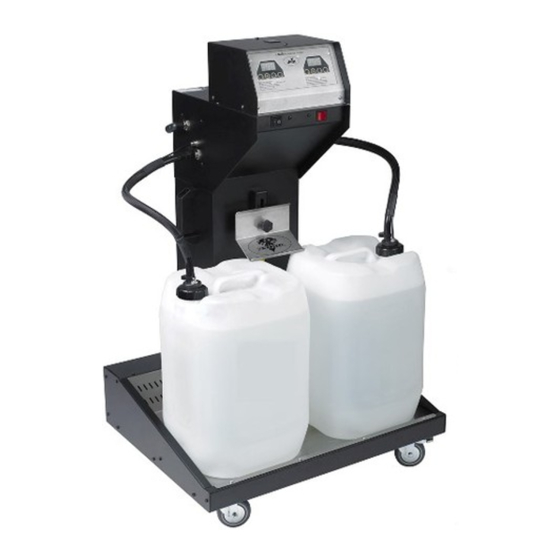
Page 7: Product Overview
Product overview data and power control panel power fluid line output pump control fluid tank hose fluid tank holder 25 liter fluid tank mounting bracket data, power, fluid, and address smoke output nozzle Product overview... -
Page 8: Rear Panel Details
Rear panel details Rear Panel of Base A remote control input AVR socket (service use) B 5-pin XLR DMX out G Hydra data line in C 5-pin XLR DMX in H Hydra data line out D 3-pin XLR DMX in AVR socket (service use) E 3-pin XLR DMX out Rear Panel of Head... -
Page 9: Introduction
If a leak should occur, the Hydra will detect it and shut itself down. Congratulations on your purchase of the Hydra smoke system from Jem. Details of the full range of Jem products are available on our website at www.jemsmoke.com. -
Page 10: Installation
Installation DANGER! DO NOT install or operate the Hydra until you have read and observed all the precautions listed in “Safety information” on page 3. I n c l u d e d i t e m s The standard Hydra system is supplied with: •... -
Page 11: Head Location Requirements
H e a d lo c a t i o n r e q ui r e m e n t s The Hydra head’s nozzle can reach 220°C (428° F). The heads must be positioned well out of reach of the public, so that accidental contact with the head is impossible. -
Page 12: Fluid Line Connections
D a t a c a b l e The Hydra system requires data cables designed for RS-485 use, available from your Jem dealer, to connect the base with the heads. Audio cable may work to some degree, but it is not designed for data transmission and its use may result in erratic performance. -
Page 13: Connecting The Data Line
AC voltage is appropriate for your model, as indicated on the machine’s serial number label. If your AC voltage is outside the appropriate range, do not use the machine. Contact Jem Service for assistance. Installation... -
Page 14: Head Address Setting
I n s t a l l i n g h e a d s H e a d a d d re s s s e t t i n g Each Hydra head must be assigned a unique address to identify it within the system. The address is set with the 16-position dial on the rear panel. -
Page 15: Fluid System
DANGER! The Hydra can run safely only on the specific smoke fluids it is designed for. Use ONLY the Jem smoke fluids designated in this manual. NEVER use any other type of fluid, or toxic gas may be produced. You will probably also cause damage to the system that is not covered by the product warranty. -
Page 16: Control Panel
Control panel O v e r v i e w The Hydra control panel consists of two LED displays and two toggle switches. menu enter down The displays allow you to • read status messages and sensor values, • modify user settings, •... -
Page 17: Menu Key
CaL Err the calibration values for the pressure sensors cannot be read. Turn off the base. If the message still appears after turning the machine on again, contact Jem Service. Adr 025 the base is ready for DMX operation. The number displayed is the DMX address. -
Page 18: Flu (Fluid Control) Setting
B a s e c o n t r o l m e n u ( f l u i d c o n t r o l ) s e t t i n g The fluid control setting determines how the system changes from one tank to the other. When set to (automatic), the system switches tanks automatically. -
Page 19: P T (Target Pressure) Setting
( t a r g e t p r e s s u r e ) s e t t i n g The target pressure setting determines the pressure in the fluid line. The range is 30 to 42 psi; the default value is 36 psi and works in most applications. -
Page 20: Hot (Head Temperature) Setting
The options are (low), (medium), and (high); the default value is . The correct setting for each approved fluid is shown below. Jem Fluid Setting Pro Steam Simulation Fluid n o r Regular DJ Fluid (DJ mix) Pro Smoke Super (ZR mix) Pro Smoke High Density Check the setting when starting the system and whenever refilling the fluid tanks. -
Page 21: Alt (Alternate Menu) Setting
( t i m e - o f f ) s e t t i n g The time-off setting determines the wait interval when using the timer to control the Hydra in stand-alone mode. The wait interval may range from 0 to 90 seconds; the default value is 2 seconds. Set as follows: 1. -
Page 22: Remote Control
REMOTE on the rear panel of the Hydra base. The remote control is powered through its cable by the Hydra base; no batteries are required. The cable may be extended to up to 25 m (82 ft.) with a 3-pin XLR DMX cable, available from your Jem dealer. -
Page 23: Dmx Control
For best results, use cable designed for high speed digital data transmission. Suitable DMX cable is available from your Jem dealer. D M X a d d r e s s a n d c h a n n e l s The Hydra’s address setting must match the DMX address allocated to it on the controller. -
Page 24: General Operation
AC power, the heat exchangers switch on when the base is switched on.) 3. Check the fluid tanks. Refill with an approved Jem fluid and prime as required. If changing to a different fluid, please see “Transition between fluid types” on page 15. -
Page 25: Fluid Consumption
The simplest way to generate smoke is to execute the run menu’s on and off commands from the control panel or, if you have the Jem Remote Control, to press the Fog button. This fires all heads at the level determined by the fog level setting. -
Page 26: Priming The Fluid Line
T o u r i n g w i t h t h e H y d r a A custom flight case is available for transporting the Hydra base. Contact your Jem supplier for information. The base hose fluid caps are not leakproof. Remove the fluid tank hoses from the tanks for transportation and seal the tanks with regular caps. -
Page 27: Basic Service
Before servicing the Hydra, read and observe all the precautions listed in “Safety information” on page 3. Any service not described in this section must be carried out by a Jem service technician. C l e a n i n g Excessive dust, smoke fluid, and dirt buildup will degrade performance and cause overheating and damage to the machine that is not covered by the product warranty. -
Page 28: Fuse Replacement
Remove the spent fuse and replace with one of exactly the same size and rating. The fuse type is indicated on the serial number label. Contact Jem Service if the fuse blows repeatedly. A n n u a l p r e s s u r e c h e c k In order to reduce the cycling of the pump to a minimum, a diaphragm accumulator is used to store pressurized liquid in the base unit. -
Page 29: Troubleshooting
Terminate data line as described under Missing or incorrect termination “Hydra terminators” on page 12. Head reports error (status reads “E”) Head malfunction Contact Jem Service Heads don’t fire and “off” message Leak detected See “Diagnosing leaks” on page 27 displayed “Flu out”... -
Page 30: System Diagrams
System diagrams System 1:One fluid line with self-seal connectors, base at end of Hydra data line Tee connector 10 mm cap plug 6 mm adaptor 6 mm self-seal connector 10 mm self-seal connector 10 mm tubing 6 mm tubing Hydra data line Hydra terminator Hydra user manual... - Page 31 System 2: Two fluid lines, base in middle of Hydra data line Tee connector 10 mm cap plug 6 mm adaptor 6 mm self-seal connector 10 mm self-seal connector 10 mm tubing 6 mm tubing Hydra data line Hydra terminator System diagrams...
- Page 32 System 3: Fluid line connected in ring, base at end of Hydra data line Tee connector 10 mm cap plug 6 mm adaptor 6 mm self-seal connector 10 mm self-seal connector 10 mm tubing 6 mm tubing Hydra data line Hydra terminator Hydra user manual...
-
Page 33: Hydra Specifications
Jem Hydra head, 230 V, 50/60 Hz ........ - Page 34 Control options ........
- Page 36 www.martin.com • Olof Palmes Allé 18 • 8200 Aarhus N • Denmark Tel: +45 8740 0000 • Fax +45 8740 0010...
Need help?
Do you have a question about the MARTIN Hydra and is the answer not in the manual?
Questions and answers