Table of Contents
Advertisement
Quick Links
Package Contents
EdgeRouter ER-12
Ground Screw
Installation Requirements
Wall-mounting (optional)
Drill with 6 mm drill bit
Phillips screwdriver
For indoor applications, use Category 5 (or above) UTP cabling approved for
indoor use.
For outdoor applications, shielded Category 5 (or above) cabling should be used
for all wired Ethernet connections and should be grounded through the AC
ground of the power supply.
We recommend that you protect your networks from harmful outdoor
environments and destructive ESD events with industrial-grade, shielded
Ethernet cable from Ubiquiti. For more details, visit:
Note:
Although the cabling can be located outdoors, the EdgeRouter itself
should be housed inside a protective enclosure.
ER-12 Quick Start Guide
Wall Mount Screws (Qty. 2)
Power Adapter (24V, 1A)
Wall Mount Anchors (Qty. 2)
Cable Clip
ui.com/toughcable
Advertisement
Table of Contents

Related Manuals for Ubiquiti ER-12


Summary of Contents for Ubiquiti ER-12
- Page 1 We recommend that you protect your networks from harmful outdoor environments and destructive ESD events with industrial-grade, shielded Ethernet cable from Ubiquiti. For more details, visit: ui.com/toughcable Note: Although the cabling can be located outdoors, the EdgeRouter itself...
-
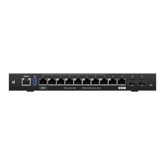
Page 2: Hardware Overview
We recommend that you update the EdgeRouter to the latest firmware. System LED Flashing White Bootup in progress. Ready for use, not connected to Ubiquiti® White Network Management System (UNMS™). Blue Ready for use, connected to UNMS. Steady Blue with... -
Page 3: Wall Mounting
SFP Link /Act LED (Ports 10 - 11) No Link Green Link Established at 1 Gbps Green Flashing Link Activity at 1 Gbps Console RJ45 serial console port for Command Line Interface (CLI) management. RJ45 (Ports 0 - 9) All RJ45 ports can be used for routing and support 10/100/1000 Mbps Ethernet connections. -
Page 6: Connecting Power
Grounding (Recommended) The Power Adapter grounds the device; however, you can add optional ESD grounding for enhanced ESD protection. 1. Attach the Ground Screw to secure a ground wire (not included) to the Grounding Point. 2. Optional: To secure the Power Adapter cord, insert it into the Cable Clip and secure the Cable Clip using the Ground Screw. - Page 7 Connect the Power Adapter to the Power port and a power outlet. Using SFP Ports...
- Page 8 For information about compatible fiber SFP modules, visit: ubnt.link/SFP_DAC_Compatibility Accessing the EdgeOS Configuration Interface The EdgeOS® configuration interface can be accessed via DHCP or static IP address assignment. By default, eth1 is set up as a DHCP client, while eth0 is assigned a static IP address of 192.168.1.1.
-
Page 9: Static Ip Address
3. Launch your web browser. Enter the appropriate IP address in the address field. Press enter (PC) or return (Mac). 4. Enter ubnt in the Username and Password fields. Read the Ubiquiti License Agreement, and check the box next to I agree to the terms of this License Agreement to accept it. -
Page 10: Specifications
4. Enter ubnt in the Username and Password fields. Read the Ubiquiti License Agreement, and check the box next to I agree to the terms of this License Agreement to accept it. Click Login. The EdgeOS Configuration Interface will appear, allowing you to customize your settings as needed. -
Page 11: Safety Notices
ER-12 LEDs System Power Data Ports Speed/Link/Activity; PoE (Ports 0 and 9 only) SFP Data Port Link/Activity Processor 4-Core 1 GHz MIPS64 System Memory 1 GB DDR3 RAM On-Board Flash Storage 4 GB eMMC, 8 MB SPI NOR ESD/EMP Protection Air: ±... -
Page 12: Electrical Safety Information
remote risk of electric shock from lightning. Electrical Safety Information 1. Compliance is required with respect to voltage, frequency, and current requirements indicated on the manufacturer’s label. Connection to a different power source than those specified may result in improper operation, damage to the equipment or pose a fire hazard if the limitations are not followed. -
Page 13: Declaration Of Conformity
CE Marking CE marking on this product represents the product is in compliance with all directives that are applicable to it. WEEE Compliance Statement Declaration of Conformity Online Resources © 2021 Ubiquiti Inc. All rights reserved.
Need help?
Do you have a question about the ER-12 and is the answer not in the manual?
Questions and answers