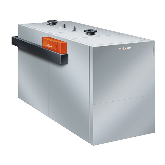
Viessmann Vitocrossal 200 Installation Instructions For Contractors

Viessmann Vitocrossal 200 Installation Instructions For Contractors

Gas condensing boiler for open flue and room sealed operation
Hide thumbs Also See for Vitocrossal 200:

Advertisement

Quick Links

VIESMANN
Installation instructions
for contractors
Vitocrossal 200
Type CM2C, 75 to 311 kW
Gas condensing boiler
For open flue and room sealed operation
VITOCROSSAL 200
Dispose after installation.
5799212 GB/en 12/2017

Advertisement

Table of Contents
loading

Summary of Contents for Viessmann Vitocrossal 200

  • Page 1 VIESMANN Installation instructions for contractors Vitocrossal 200 Type CM2C, 75 to 311 kW Gas condensing boiler For open flue and room sealed operation VITOCROSSAL 200 Dispose after installation. 5799212 GB/en 12/2017...
  • Page 2 Safety instructions Please follow these safety instructions closely to prevent accidents and material losses. Safety instructions explained Danger Note This symbol warns against the risk of injury. Details identified by the word "Note" contain additional information. Please note This symbol warns against the risk of material losses and environmental pollution.
  • Page 3: Table Of Contents

    Index Information Disposal of packaging ................Symbols ....................Intended use ..................Product information ................Conversion for other countries ............... Preparing for installation Clearance dimensions ................Installation sequence Siting and levelling the boiler ..............Removing the base frame for handling (if necessary) ......■...
  • Page 4: Information Disposal Of Packaging

    Please dispose of packaging waste in line with statu- DE: Use the disposal system organised by tory regulations. Viessmann. AT: Use the ARA statutory disposal system (Altstoff Recycling Austria AG, licence number 5766). CH: Packaging waste is disposed of by the HVAC contractor.
  • Page 5: Product Information

    Thermal insulation, burner, electronics unit with cable harnesses and programming unit packed separately Conversion for other countries The Vitocrossal 200 may only be delivered to the countries specified on the type plate. For deliveries to other countries, approved contractors must arrange individual approval on their own initiative and in accordance with the law of the country in question.
  • Page 6: Preparing For Installation Clearance Dimensions

    500 C 500 (250) Fig. 1 Boiler Dimensions for installation as a two-boiler system Burner with Viessmann accessories: Installation instructions for flue gas header and hydraulic system connection Clearance for adjusting the side panels Dimensions in brackets are minimum clearances.
  • Page 7: Installation Sequence Siting And Levelling The Boiler

    Siting and levelling the boiler Please note Note Damage to the flue gas connection can result in A suitable condensate drain must be available in the leaks. installation room. If the boiler is installed at ground Never lift or move the boiler by the flue gas con- level, the condensate drain must be no more than nection.
  • Page 8: Removing The Base Frame For Handling (If Necessary)

    Siting and levelling the boiler (cont.) Removing the base frame for handling (if necessary) If necessary, the base frame can be removed for han- Danger dling. If the boiler is not secured, it can slide off the base frame and cause injury. Secure the boiler body.
  • Page 9: Mounting The Burner

    Mounting the burner Changing the burner fixture to open on the right (if necessary) 18 Nm Fig. 4 1. Remove the four M10 nuts with washers and the 2. Attach the hinge bracket to the threaded pins on hinge bracket. the right-hand side in reverse order.
  • Page 10: Mounting The Burner

    Mounting the burner (cont.) Mounting the burner 18 Nm Fig. 5 1. Hook the burner onto the hinge bracket and secure 3. Check that the gap between the boiler front panel with the split pin. and the hinge bracket is 16 mm 0.5 mm, so that ±...
  • Page 11: Fitting The Electronics Unit

    Fitting the electronics unit Fig. 6 1. Fit the rear thermal insulation mat. 4. Connect the earth cable of the electronics unit to the blade terminal contacts in the bracket. 2. Secure the electronics unit to the bracket. 5. Connect the earth cable supplied for the cover 3.
  • Page 12: Fitting The Thermal Insulation And Casing

    Fitting the thermal insulation and casing Note All required components are included in the thermal insulation box. Thermal insulation mats Fig. 7 Secure all thermal insulation mats with spring hooks.
  • Page 13: Pre-Assembling The Side Panels

    Fitting the thermal insulation and casing (cont.) Pre-assembling the side panels Fig. 8 1. Lay the side panels for the front, centre and back 2. Secure the guide rails (with sliding profile) to the on a suitable surface (e.g. packaging materials) side panels with screws through the installation and align.
  • Page 14: Fixing Rails And Retaining Brackets

    Fitting the thermal insulation and casing (cont.) Fixing rails and retaining brackets Fig. 9 1. Bottom fixing rails: Secure with screws to the base 3. Position the pre-assembled side panels with the rails, flush with the front. guide rails at the bottom, then hook onto the tabs in the fixing rails at the top.
  • Page 15: Front Of Top Panel And Programming Unit

    Fitting the thermal insulation and casing (cont.) Front of top panel and programming unit Fig. 10 01. Attach the gas spring to the right or left-hand fixing 03. Secure the crossbar to the upper rails of the boiler rail. using two M6 screws. 02.
  • Page 16 Fitting the thermal insulation and casing (cont.) Fig. 11 04. Insert the programming unit into the opening in the 06. Secure the control unit panel to the front of the top control unit panel from the inside. panel with two screws Ø 4.8 mm and four M6 Secure the programming unit with 4 screws screws.
  • Page 17 Fitting the thermal insulation and casing (cont.) Fig. 12 07. Carefully push open the right and left-hand sliders 09. Insert one M6 screw halfway into the right-hand on the programming unit. side panel and likewise another into the left-hand side panel. 08.
  • Page 18: Fitting The Connecting Cables

    Fitting the thermal insulation and casing (cont.) Fitting the connecting cables Fig. 13 1. Secure data cables to the top left-hand fixing 2. Secure 230 V cables to the top right-hand fixing rail using the cable ties provided, as shown in the rail using the cable ties provided, as shown in the diagram.
  • Page 19 Fitting the thermal insulation and casing (cont.) Fig. 14...
  • Page 20 Fitting the thermal insulation and casing (cont.) Inserting the plugs into the gas burner control unit and burner Fig. 15 1. Insert the data cable plugs as shown in the dia- Please note gram. Cables can be damaged by high temperatures. Prevent contact with hot components.
  • Page 21 Fitting the thermal insulation and casing (cont.) Inserting the plugs into the programming unit Fig. 16 230 V cable Data cable to the control unit LAN cable to the back of the boiler Insert the 230 V cable plugs and data cable plugs as shown in the diagram.
  • Page 22 Fitting the thermal insulation and casing (cont.) Inserting the plugs into the electronics unit and the back of the boiler 15A/15B Fig. 17 1. Insert the data cable plugs as shown in the dia- 3. Guide all cables in through the base of the control gram.
  • Page 23: Back Panels

    Fitting the thermal insulation and casing (cont.) Back panels Fig. 18 1. Secure the right and left-hand retaining rails to the 5. Align the back panels. top and bottom of the fixing rails using screws. Check whether the seal of the electronics unit fits closely against the top back panel.
  • Page 24: Connections On The Heating Water Side

    Connections on the heating water side SA/KR2 Fig. 19 Drain and expansion vessel connection R 1 KR2 Boiler return 2 (accessories, subject to order) KOA Condensate drain with trap R Boiler flow ½ Boiler return Safety connection G and R 1 ½...
  • Page 25: Making The Safety Connections

    Making the safety connections 1. Make the safety connections. Safety valve Install all pipe connections free of load and torque stress. Equip boilers with a safety valve that is individually tes- ted to EN 12828 and is marked according to the sys- 2.
  • Page 26: Fitting The Top Panels And The Top Back Panel

    Fitting the top panels and the top back panel Fig. 20 1. Insert the top left-hand panel. Push the front tab 3. Secure both top panels with screws Ø 4.8 mm. into the slot in the front crossbar. 4. Connect the earth cable to the top back panel. 2.
  • Page 27: Connections On The Flue Gas Side

    Connections on the flue gas side Flue gas connection and trap Fig. 21 1. Insert the boiler flue connection (accessories) into Do not carry out commissioning until the following the flue outlet as far as it will go. conditions are met: Free passage through the flue gas pipes.
  • Page 28: Condensate Drain Pipe

    Connections on the flue gas side (cont.) Condensate drain pipe Fig. 22 Route condensate drain with a fall and below the anti- Connect the neutralising system to the drainage sys- flooding level of the flue gas collector. tem. Condensate drain must be accessible for inspec- Neutralising system installation instructions tion.
  • Page 29 Gas connection (cont.) Fig. 23 1. Break out the aperture for the gas line at the perfo- 5. Carry out a tightness test. ration in the right or left-hand side panel. Please note 2. Route the gas line through the aperture in the side Excessive test pressure will damage the panel.
  • Page 30: Commissioning And Adjustment

    Commissioning and adjustment Service instructions for boiler and boiler control unit Front panel 1. 2x 2. 2x Fig. 24 1. Insert 2 location studs into the front panel and 4. Pivot the front panel closed and click it into place. secure.
  • Page 32 Viessmann Werke GmbH & Co. KG Viessmann Limited D-35107 Allendorf Hortonwood 30, Telford Telephone: +49 6452 70-0 Shropshire, TF1 7YP, GB Fax: +49 6452 70-2780 Telephone: +44 1952 675000 www.viessmann.com Fax: +44 1952 675040 E-mail: info-uk@viessmann.com...

This manual is also suitable for:

Cm2c

Table of Contents