Table of Contents
Advertisement
Quick Links
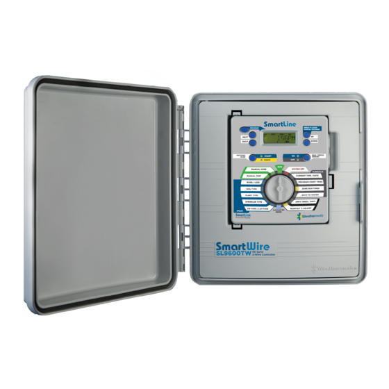
9600TW 96-Zone
2-Wire Controller
Owner's Manual
PROGRAM
PGM
NEXT
BACK
WATERING
SMART
MODE
BASIC
MANUAL ZONE
MANUAL TEST
MORE / LESS
SOIL TYPE
PLANT TYPE
SPRINKLER TYPE
ZIP CODE/LATITUDE
SMART
PRESS TO START
MANUAL PROGRAM
UP
DOWN
RAIN/FREEZE
ON
SENSING
OFF
RUN
SYST E M O F F
CURRENT TIME / DATE
PROGRAM START TIMES
ZONE RUN TIMES
DAYS TO WATER
OMIT TIMES / DAYS
SEASONAL % ADJUST
ADVANCED
MENU
BASIC
Advertisement
Table of Contents
Troubleshooting

Related Manuals for Weathermatic SmartWire 9600TW


Summary of Contents for Weathermatic SmartWire 9600TW
- Page 1 PROGRAM PRESS TO START MANUAL PROGRAM NEXT BACK DOWN WATERING RAIN/FREEZE SMART MODE SENSING BASIC 9600TW 96-Zone MANUAL ZONE SYST E M O F F 2-Wire Controller BASIC MANUAL TEST CURRENT TIME / DATE MORE / LESS PROGRAM START TIMES Owner’s Manual SOIL TYPE ZONE RUN TIMES...
- Page 2 Smart mode will analyze “on site” weather data to automatically set optimum watering times for each zone, based on Weathermatic’s patented methodology. Smart Mode will Scan with smartphone to also save water by automatically setting run and soak cycles to go to web-based help.
- Page 3 Rain Sensor for All Wireless rain/ SLCAM Clamp-on Amp Meter SmartLine® Models freeze sensor SLCONN Specialty Wire Connector SLWIRE 2-conductor, jacketed UL/UF approved for direct burial SmartWire accessories available through your professional Weathermatic installer. For the Weathermatic distributor directory, go to www.weathermatic.com.
-
Page 4: Table Of Contents
Table of Contents How it Works ............. 1 Manual Start Functions .......... 14 Manual Zone ..............14 Getting Acquainted With Your SmartWire 8.2 Manual Test ................14 SL9600TW Controller ..........2 Getting Acquainted With Your SL9600TW Programming for Smart Watering Mode .... 14 Control Panel .............. - Page 5 Table of Contents 10.3.7 RUNTIME ................23 10.21.1 MODEL .................. 26 10.3.8 TOTL RUN ................23 10.21.2 VERSION ................26 10.3.9 CLR TOTL ................23 10.21.3 BUILD ................... 26 10.3.10 CLR DEF ................23 10.22 GROW IN ................26 10.4 RAIN DLY ................23 10.23 DEFAULT ................
- Page 6 Build Your SmartLink Network You can now expand your SmartLine controller to maximize water savings, improve efficiency and improve landscape beauty. Add an on-site Weather Sensor that not only reads rain/freeze data, but also automatically adjusts for the local temperature and conditions that may impact your landscape's need for water.
-
Page 7: How It Works
Install every 500 ft trenching, simplicity of wiring and troubleshooting and ease of expansion when additional zones are needed. Weathermatic SmartWire™ 2-Wire allows for connection of up to 3 separate 2-wire paths to simplify installation on larger projects. -
Page 8: Getting Acquainted With Your Smartwire Sl9600Tw Controller
This is like having 4 controllers in one. You ZIP CODE/LATITUDE SEASONAL % ADJUST can assign zones to any of the 4 programs, ADVANCED SMART MENU NEXT NEXT allowing for complete flexibility of your irrigation schedule. Programs A, B, C, and D can be programmed BACK BACK http://support.weathermatic.com... - Page 9 RUN or pause. SYSTEM OFF. The program in operation will resume when you return the dial to RUN or if there is no programming activity for 30 minutes. http://support.weathermatic.com...
-
Page 10: Quick View
SLHUB, see decoder/ clear errors SLW in Advanced Menu for instructions. If you are using a rain/ freeze sensor connected to your controller at the SEN terminals, see SENSOR in Advanced Menu for instructions. http://support.weathermatic.com... -
Page 11: Planning Your 2-Wire Layout
The system will work Last Last Decoder Decoder with most wiring configurations if the wire length requirements SL9600TW are met. (Note: Keep BLACK to BLACK and RED to RED when wiring the communication wire.) Last Last Decoder Decoder Combination Last SL9600TW Decoder http://support.weathermatic.com... -
Page 12: Attaching Components
SLCONN Grade Maximum total wire path length is 10,000 . (3,048 m). Waterproof Valve Box wiring Weathermatic recommends the use of SLWIRE cable connectors specifically designed for an irrigation control system and Decoder complying with the following specifications: 2-Wire path Expansion •... -
Page 13: Lightning Protection
4.0 Lightning Protection SLCONN 4.0 Lightning Protection Waterproof Weathermatic SLGDT gas discharge tube lightning arrestors wiring connector 1 Station must be used on all 2-wire grids. The SLGDT lightning arrestor To SLM48DM attaches directly to the 2-wire system and helps dissipate 2 Station static electricity generated by a nearby lightning strike. -
Page 14: Grounding Requirements
Some sites require a 6” diameter hole to be augured and backfilled with Ground Enhancement o Soil and/or Ground Enhancement Materials. Materials. • Ground Rods/Plates must be installed in a 6” min. valve box, 6” below grade or below frost line, located within an http://support.weathermatic.com... -
Page 15: Connecting The Sl9600Tw 2-Wire Controller
Zone 97 or zone 98 for use with the pump start relay or master valve. Zone 97 will be associated with MV1 and Zone 98 will be associated with MV2. Step 3: You are ready to program your decoders. The http://support.weathermatic.com... -
Page 16: Decoder Programming Steps
When combined with a in the display window. Note: When you are programming Weathermatic SLW Weather Sensor, Smart mode gives you the a multi-valve decoder, the display will only show the zone power to reduce water waste. Many water districts are offering number for the first zone to be assigned to that decoder. -
Page 17: Using The Programming Buttons
OMIT TIMES / DAYS different position. ZIP CODE / LATITUDE ZIP CODE / LATITUDE SEASONAL % ADJUST SEASONAL % ADJUST designate and will water all zones with ADVANCED ADVANCED SMART SMART MENU MENU set Zone Run Times for that program. http://support.weathermatic.com... -
Page 18: Zone Run Times
(PGM) selection showing in the display. You can select a different watering schedule for each program if you wish. If you select DAYS, then use the NEXT button to step through each day of the week and the UP and DOWN buttons to select http://support.weathermatic.com... -
Page 19: Omit Times/Days/Dates (Optional)
ZIP CODE / LATITUDE ZIP CODE / LATITUDE SEASONAL % ADJUST SEASONAL % ADJUST If a watering program in progress ADVANCED ADVANCED SMART SMART MENU MENU is paused for a blackout period, the ORANGE LED will display http://support.weathermatic.com... -
Page 20: Seasonal % Adjust (Optional)
POSITION. 9.0 Programming for Smart Watering Mode 8.0 Manual Start Functions Weathermatic’s patented SMART mode overrides user assigned zone run times and calculates zone run times based on the The SmartLine® controller has two dial positions for manual location of the site, inputs by zone, and weather readings system starts: from the SLW Series On-Site Weather Sensor. -
Page 21: Set Zip Code Or Latitude
UP and DOWN buttons to scroll past the sprinkler types and select that number. For USA users, inches per hour will be displayed (.2 to 3.0 inches per hour). Numeric precip rate resolution is 0.01 in/hr below http://support.weathermatic.com... -
Page 22: Plant Type For Zones
% designations of 10 to 300%. For selecting Advanced Menu, Review and Run/Soak. example, a Native plant zone might be assigned 30% rather the default of 25%. As a rule in SMART mode, the higher the plant http://support.weathermatic.com... -
Page 23: More/Less (Optional)
(Note: The icon will flash for 1 minute at the time of a communication. The icon will be static between communication This feature can be useful to reduce run time adjustments for events.) The antenna indicates communication has been shady and partially shaded zones. The table provided may http://support.weathermatic.com... -
Page 24: Mode Button
MODE button will flash the SMART LED to RED and then return to the BASIC mode. When this occurs, you can press and hold the MODE button to see a scrolling message indicating the reason SMART mode is not available. http://support.weathermatic.com... -
Page 25: Advanced Menu
[CLR TOTL] [DELAY] [FLOW] [HIGH PK] [TOTL RUN] [FREEZE] [SLW] [RAIN] [RUNTIME] [DEFICIT] [RAIN DLY] [RUN/SOAK] [NEXT RUN] [BATTERY] [SKIP CUR] [LOCATOR] [SLW] [LAST COM] [24V PWR] [TEMP DATA] [REVIEW] [BATTERY] [ADVANCED FUNCTIONS] [TESTS] [OUTPUTS] [FAULTS] [ON] [OPEN FLT] [OFF] http://support.weathermatic.com... -
Page 26: Fault
SLW Weather Sensor sends another on successfully. message that indicates a good battery. The fault will also clear if no communication is received for a full day (i.e. communication failure). See Section 7.3 Replacing SLW Series Weather Sensor Battery. http://support.weathermatic.com... -
Page 27: Tests
5 days. Press NEXT to view daily high and low readings for the screen. SL9600TW controllers use a Real Time Calendar the prior day. Continue pressing NEXT to view up to 5 days of Clock instead of a backup battery to maintain correct time temperature history. http://support.weathermatic.com... -
Page 28: Slw
This is the minimum time the volume of flow per zone and the ability to clear the monitored zone must soak before it is ready to run again. SMART Run/Soak values. times can be changed by adjusting the soil and slope settings http://support.weathermatic.com... -
Page 29: Runtime
The freeze selection is on/off toggle to override the SLW freeze To clear deficits, press NEXT. Use UP or DOWN buttons to select sensor feature for selected zones. Factory default is ON for all KEEP or CLEAR. Press NEXT or BACK to exit CLEAR DEFICITS. zones. http://support.weathermatic.com... -
Page 30: Delay
Your controller is programmed with the a default of starting watering pauses for the specified soak time. Use PGM button Daylight Saving Time starting on the second Sunday in March to select program. Use UP and DOWN buttons to set RUN time http://support.weathermatic.com... -
Page 31: Num Start
30 minutes; adjustable in 10 minute increments from 30 minutes to 3 hours. 10.16 NC/NO MV Enter this menu to select between normally open or normally closed master valves for master valve 1 and master valve 2. http://support.weathermatic.com... -
Page 32: Con
Step 1: Set up your long-term SMART or BASIC watering programs have been cleared. Note: This function is not the same program. as the Total Master Reset as described under 7.1 in your Owner’s Step 2: Go to Advanced Menu and select DEFAULT. Press Manual. http://support.weathermatic.com... -
Page 33: Default
RED or ORANGE LED as shown in the table and the reason for the pause will be displayed. 10.24 UNITS This setting allows for you to choose either STANDARD (United States customary units) or METRIC. Press the BACK button when the display reads your desired selection. http://support.weathermatic.com... -
Page 34: Changing Slw Or Rfs5 Batteries
Note: The SLW Battery function is visible Time after you have established communication with the SLW. Orange Green SOAK Zone waiting for soak time Orange Green ZONE Waiting for next zone valve to open Orange Green PAUSE Waiting for MVP to turn on or off http://support.weathermatic.com... -
Page 35: Troubleshooting Guide
RED—The SLW is defective and should be replaced. Fourth Blink Red—Communication problem is in the cable or SLHUB or RF signal problem on wireless units. If all SLW diagnostic blinks are GREEN, all SLW functions and communications between the SLW and SLHUB are working properly. Recheck data entry required into controller. http://support.weathermatic.com... - Page 36 Pause for Run/Soak in progress. This is normal operation to allow water expected run time infiltration and prevent runoff Check seasonal % settings if BASIC mode is in use. Module not installed Install module No initial AC power-up of controller Connect AC power and close control panel http://support.weathermatic.com...
- Page 37 Omit times/days are activated Verify omit times/days Rain or freeze sensor has stopped Replace sensor if faulty watering (Sensor LED is red Select OFF mode if desired Reset start time to later in the day to avoid early morning freezing temperatures. http://support.weathermatic.com...
-
Page 38: Troubleshooting The Sl9600Tw Module
This feature will create a “chatter” for a selected addresses will be displayed rotating every three seconds valve as a convenient method of locating buried valves. Use until the zone is turned off. NEXT and BACK buttons to scroll to the valve you want to “chatter.” http://support.weathermatic.com... - Page 39 Cause: high temperature, excessive 2-wire duty cycle at temperature. Temperature Action: shade controller, replace SL9600TW. Shut Down Decoder Cause: multiple decoders at one time, decoder removed before program cycle completes, failed decoder, Programming failing SL9600TW. Failure Action: retry, replace decoder, replace SL9600TW. http://support.weathermatic.com...
-
Page 40: Special System Features
• Input voltage 24 - 28 VAC over the 2-wire system. configuration process. • The Weathermatic SL9600TW can support a total of 96 • Valves are actuated by a command from the decoder. valves plus 2 master valves. A maximum of 5 valves including master valve or pump relay can be operated concurrently. -
Page 41: World Latitudes
80 N 70 N 60 N 50 N 30 N 20 N 10 N 10 S 20 S 30 S 40 S 50 S 60 S 70 S 80 S... -
Page 42: Basic Programming Table
www.weathermatic.com... - Page 44 www.weathermatic.com...
- Page 46 www.weathermatic.com...
- Page 48 AD431_revC...
Need help?
Do you have a question about the SmartWire 9600TW and is the answer not in the manual?
Questions and answers