Table of Contents
Advertisement
Quick Links
Advertisement
Table of Contents

Subscribe to Our Youtube Channel
Related Manuals for Sliger SV540


Summary of Contents for Sliger SV540
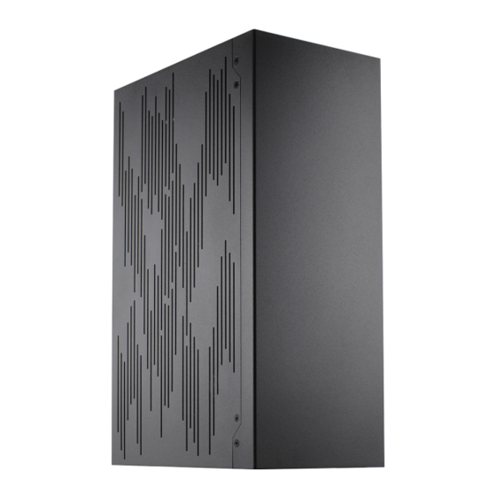
- Page 1 SV540 Vertical Mini-ITX PC Case - Build Guide V2.0...
- Page 2 SCREWS The SV540 comes with a total of 5 different screws. For the purposes of this guide we will assign a unique color to each of screw to signifying their locations throughout this guide. GREEN M3 x 6mm PAN HEAD...
- Page 3 TOOL-LESS END CAPS The SV540s top and bottom covers feature tool-less removal via ball-stud mounting points. This feature allows for convenient access to your motherboard and PCIe card IO ports regardless of case orientation. The top and bottom panels can also be reversed onto either end of the case, allowing the “cable cubby”...
-
Page 4: Panel Removal
PANEL REMOVAL The front panel is the only panel that will stay in place without the screws. The easiest method to remove the front is to first remove the side panels, and then push against front panel from inside the case. - Page 5 CASE FRAME The rear radiator mount bracket of the SV540 frame is held on by 6x 6-32 X 1/4” FLAT HEAD screws; two on each side of the cable cubby, and one on each side at the opposite end of the case.
-
Page 6: Power Cord
POWER CORD The SV540 includes an internal power cord extension, protective grommet, and mount bracket for routing the power supply inlet into the"cable cubby" of the case frame. Clip the Cable Grommet onto the power cord before you install it into the case, then run the cord through the cutout located above the PCIe card tab cutout, and finally slide the grommet into position as shown below. -
Page 7: Power Button
POWER BUTTON SV540 has the ability to mount the power button to either end of the case frame. The power button is attached to a small bracket which can be relocated to either mounting position. This bracket is secured to... - Page 8 MOTHERBOARD Don’t forget to install the power cord and your IO shield first! Some CPU coolers may require a back plate installed before installing the motherboard into the case. It is advised to also check that any M.2 mounts on the back of the motherboard have drives installed before mounting the motherboard.
-
Page 9: Power Supply
POWER SUPPLY NOTE: The fan on the power supply is recommended to be positioned with the fan side pointed towards the center spine of the case. This orientation will result in better overall system temperatures and lower noise. Once positioned, the SFX PSU can be attached to the PSU Mounting Bracket with up to 6x of the included 6-32 x 1/4”... - Page 10 SSDs and HDDs Our SV540 has multiple 3.5" HDD and 2.5" SSD mounting locations. Shown below are various HDD and SSD configurations. 2.5" SSD should be mounted with 2x M3 x 5mm FLAT HEAD screws for each SSD.
- Page 11 SSDs and HDDs Cont. 3.5” HDD should be mounted with up to 3x 6-32 X 1/4” FLAT HEAD screws.
-
Page 12: Cable Management
CABLE MANAGEMENT Once the motherboard and power supply are mounted, it is recommended to do some cable management before installation of any radiators or PCIe cards. Note: the CPU and cooler mount back plate / standoffs are installed. The power switch/LED is routed and plugged into the motherboard. - Page 13 PCIe riser. Slide the card into position, push down into the slot, and then secure the PCIe card bracket with the M3 PAN HEAD screws. If your GPU only has a 2-slot wide PCIe bracket the SV540 includes a single color matched Slot Cover.
- Page 14 280mm AIO ALL FANS MUST BE SET TO EXHAUST OUT THE REAR OF THE CASE If installed as intake you will cause your power supply and GPU to run at higher temperatures. If the 280mm radiator hoses are mounted at the top, you will not be able to screw the case closed as the hoses will collide with the motherboard and/or PCIe riser bracket.
- Page 15 CASE REASSEMBLY To attach the AIO/radiator, the back panel must be reinstalled from disassembly on page 5 in this guide. The rear radiator mount bracket to the SV540 frame is held on by 6x 6-32 x 1/4" FLAT HEAD screws...
- Page 16 DDC PUMP RESERVOIR SV540 has two DDC Pump / Reservoir mounting locations as shown below Location 1 Location 1: The DDC Pump attaches to DDC Pump Bracket with M4 x 5mm FLAT HEAD screws. Then it attaches to the chassis with M3 x 5mm FLAT HEAD screws.
Need help?
Do you have a question about the SV540 and is the answer not in the manual?
Questions and answers