Table of Contents
Advertisement
Advertisement
Table of Contents

Related Manuals for Encore ENHWI-G3


Summary of Contents for Encore ENHWI-G3
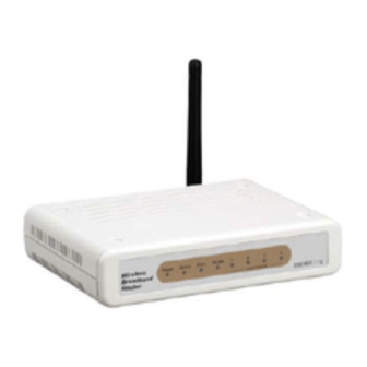
- Page 1 IEEE 802.11g Wireless Broadband Router User’s Guide...
-
Page 2: Regulatory Information/Disclaimers
Regulatory notes and statements Wireless LAN, Health and Authorization for use Radio frequency electromagnetic energy is emitted from Wireless LAN devices. The energy levels of these emissions however are far much less than the electromagnetic energy emissions from wireless devices like for example mobile phones. Wireless LAN devices are safe for use frequency safety standards and recommendations. -
Page 3: Fcc Interference Statement
FCC Radio Frequency Exposure statement This Wireless LAN radio device has been evaluated under FCC Bulletin OET 65 and found compliant to the requirements as set forth in CFR 47 Sections 2.1091, 2.1093, and 15.247 (b) (4) addressing RF Exposure from radio frequency devices. The radiated output power of this Wireless LAN device is far below the FCC radio frequency exposure limits. -
Page 4: Safety Information
Safety Information Your device contains a low power transmitter. When device is transmitted it sends out radio frequency (RF) signal. CAUTION: To maintain compliance with FCC’s RF exposure guidelines, this equipment should be installed and operated with minimum distance 20cm between the radiator and your body. -
Page 5: Table Of Contents
TABLE OF CONTENT BOUT UIDE Purpose... 1 Overview of this User’s Guide ... 1 ... 2 NTRODUCTION Applications... 2 Features... 3 NPACKING AND ETUP Unpacking... 4 Setup ... 4 ARDWARE NSTALLATION Front Panel... 5 Rear Panel ... 6 Hardware connections ... 6 Connect the Router using LAN ... - Page 6 Security ... 29 Advanced ... 32 LAN Setting... 33 Basic... 33 DHCP... 34 Access Control Setting ... 35 Filter... 35 Virtual Server... 40 Special AP... 41 DMZ... 42 Firewall Rule... 43 System Setting ... 44 Password ... 44 Time ... 45 Device Information ...
-
Page 7: About Thi Guide
Overview of this User’s Guide Introduction. Describes the Wireless Broadband Router and its features. Unpacking and Setup. Helps you get started with the basic installation of the Wireless Router. Identifying External Components. Describes the front panel, rear panel and LED indicators of the Wireless Router. -
Page 8: Introduction
INTRODUCTION With the explosive growth of the Internet, accessing information and services at any time, day or night has become a standard requirement for most people. The era of the standalone PC is waning. Networking technology is moving out of the exclusive domain of corporations and into homes with at least two computers. -
Page 9: Features
Features Compliant with IEEE 802.11g and 802.11b Devices Built-in 4 x 10/100Mbps Auto-MDIX LAN Ports Built-in 1 x 10/100Mbps Auto-MDIX WAN Port (Internet) Supports Cable/DSL Modems with Dynamic IP, Static IP, PPPoE, L2TP, PPTP or BigPond Connection Types DHCP Server Feature Allocates up to 253 Client IP Addresses Supports 64/128-bit Wired Equivalent Privacy (WEP) Supports WPA, WPA2, WPA-PSK and WPA2-PSK Advanced Security Supports MAC Address, Protocol Filters and UPnP (Universal Plug &... -
Page 10: Unpacking And Setup
Broadband Router. Do not place heavy objects on the Broadband Router. Fix the direction of the antennas. Try to place the Wireless Router in a position that can best cover your wireless network. Normally, the higher you place the antenna, the better the... -
Page 11: Hardware Installation
WLAN (ACT) This indicator lights green when there are wireless devices connected and transmitting data to the Wireless Router. LAN (Link/ACT) These indicators light green when the LAN ports were connected successfully. These indicators blink green while the LAN ports were transmitting data. -
Page 12: Rear Panel
Rear Panel The figure below shows the rear panel of the Wireless Broadband Router. Antenna There are one 2 dBi Gain Antenna in the rear panel for wireless connection. LAN (1-4) Four RJ-45 10/100Mbps Auto-MDIX ports for connecting to either 10Mbps or 100Mbps Ethernet connections. -
Page 13: Connect The Router Using Wireless Lan
Connect the Router using Wireless LAN 1. Plug in one end of the RJ45 network cable to the xDSL/Cable Modem. 2. Plug in the other end of the RJ45 network cable to the Wireless Internet Broadband Router WAN port. Check the installation The control LEDs of the Wireless Internet Broadband Router are clearly visible and the status of the network link can be seen instantly: 1. -
Page 14: Pc Network Tcp/Ip Setting
PC NETWORK TCP/IP SETTING The network TCP/IP settings differ based on the computer’s operating system (Win95/98/ME/NT/2000/XP) and are as follows. Windows 95/98/ME 1. Click on the “Network neighborhood” icon found on the desktop. 2. Click the right mouse button and a context menu will be show. 3. -
Page 15: Windows 2000
6. Select “None” for the “Gateway address” field. Figure 6. Windows 95/98/Me Gateway setup Windows 2000 Double click on the “My computer” icon on the desktop. When “My computer” window opens, open the “Control panel” and then open the “Network dialup connection” applet. Double click on the “Local area network connection”... -
Page 16: Windows Xp
Windows XP Point the cursor and click the right button on the “My Network Place” icon. Select “properties” to enter the TCP/IP setting window. 1. Set “IP address” to “Obtain an IP address automatically.” 2. Set “DNS” to “Obtain DNS server address automatically.” Figure 8. -
Page 17: Wireless Broadband Router Configuration
WIRELESS BROADBAND ROUTER CONFIGURATION First make sure that the network connections are functioning normally. This Wireless Broadband Router can be configured using Internet Explorer 5.0 or newer web browser versions. Login to the Wireless Broadband Router through WLAN Before configuring the Wireless Broadband Router through WLAN, make sure that the SSID, Channel and the WEP is set properly. -
Page 18: Configuration Menu
After entering the password, the main page comes up, the screen will display the device information. Figure 11. Device information Configuration Menu When the main page appears, find the Configuration menu in the left side of the screen. Click on the setup item that you want to configure. There are six main options: WAN, Wireless, LAN, Access Control, System and Wizard as shown in the Configuration Menu screen. -
Page 19: Setup Wizard
Setup wizard is provided as the part of the web configuration utility. User can simply follow the step-by-step process to get the wireless router configuration ready to run in 6 easy steps by clicking on the “Wizard” button on the function menu. The following screen will appear. Please click “Next”... - Page 20 Step 2: Choose time zone Select the time zone from the drop down list. Please click “Next” to continue. Figure 15. Setup Wizard – Set time zone Step 3: Set LAN and DHCP Server Set user’s IP address and mask. The default IP is 192.168.1.1. If user likes to enable DHCP, please click “Enabled”.
- Page 21 Step 4: Set Internet connection The WLAN Router will attempt to auto detect your Internet Connection. Figure 17. Setup Wizard – WAN setup - Auto detect WAN type If the WLAN Router is unable to auto detect your Internet connection, you will need to manually select the Internet connection type: Obtain IP automatically;...
- Page 22 If your ISP requires you to enter a specific host name or MAC address, please enter it in. Fixed IP Address: Figure 19. Figure 20.
- Page 23 If the Internet Service Providers assign a fixed IP address, choose this option and enter the assigned IP address, subnet mask, gateway IP and DNS IP addresses for your Broadband Router. PPPoE: Figure 21. Figure 22.
- Page 24 Obtain IP Automatically: If connected to the Internet using a PPPoE (Dial-up xDSL) Modem, the ISP will provide a Password and User Name, and then the ISP uses PPPoE. Choose this option and enter the required information. Specify IP: If connected to the Internet using a PPPoE (Dial-up xDSL) Modem, the ISP will provide a Password, User Name and a Fixed IP Address, choose this option and enter the required information.
- Page 25 PPTP: If connected to the Internet using a (PPTP) xDSL Modem, enter the your IP Address, Subnet Mask, Gateway, Server IP, PPTP Account and PPTP Password, Your Subnet Mask required by your ISP in the appropriate fields. If your ISP has provided you with a Connection ID, enter it in the Connection ID field, otherwise, leave it zero.
- Page 26 L2TP: If connected to the Internet using a (L2TP) xDSL Modem, enter the your IP Address, Subnet Mask, Gateway, Server IP, L2TP Account and L2TP Password, Your Subnet Mask required by your ISP in the appropriate fields. If your ISP has provided you with a Connection ID, enter it in the Connection ID field, otherwise, leave it zero.
- Page 27 BigPond: If your ISP is Big Pond Cable, the ISP will provide a User Name, Password, Authentication Server and Login Server IP (Optional). Choose this option and enter the required information. Figure 29. Figure 30.
- Page 28 Step 6: Restart The Setup wizard is now completed. The new settings will be effective after the Wireless router restarted. Please click “Restart” to reboot the router. If user does not want to make any changes, please click “Exit”...
-
Page 29: Wan Setting
WAN Setting This function enables users to set up the WLAN Router WAN connection, specify the IP address for the WAN, add DNS numbers, and enter the MAC address. Connection Type: Select the connection type, either DHCP client, Fixed IP or PPPoE, PPTP, L2TP or BigPond from the drop-down list. -
Page 30: Pppoe With Obtain Ip Automatically
PPPoE with Obtain IP Automatically If connected to the Internet using a PPPoE (Dial-up xDSL) Modem, the ISP will provide a Password and User Name, and then the ISP uses PPPoE. Choose this option and enter the required information. Figure 34. -
Page 31: Pppoe With Specify Ip
PPPoE with Specify IP If connected to the Internet using a PPPoE (Dial-up xDSL) Modem, the ISP will provide a Password, User Name and a Specify IP Address, choose this option and enter the required information. Figure 35. -
Page 32: Pptp/L2Tp With Obtain Ip Automatically
PPTP/L2TP with Obtain IP Automatically If connected to the Internet using a PPTP/L2TP (Dial-up xDSL) connection, enter the your Server IP, PPTP/L2TP Account and PPTP/L2TP Password, if your ISP has provided you with a DNS IP address, enter it in the DNS field, otherwise, leave it zero. Figure 36. -
Page 33: Bigpond Cable
BigPond Cable If your ISP is Big Pond Cable, the ISP will provide a User Name, Password, Authentication Server and Login Server IP (Optional). Choose this option and enter the required information. Dynamic DNS: This synchronizes the DDNS server with your current Public IP address when you are online. First, you need to register your preferred DNS with the DDNS provider. -
Page 34: Wireless Setting
Wireless setting This section enables user to set wireless communications parameters for the router's wireless LAN feature. Basic This page allow user to enable and disable the wireless LAN function, create a SSID, and select the channel for wireless communications. Figure 41. -
Page 35: Security
Security This function enables user to set authentication type for secure wireless communications. Open System allows public access to the router via wireless communications. Shared Key requires the user to set a WEP key to exchange data with other wireless clients that have the same WEP key. - Page 36 WEP: Open System and Shared Key requires the user to set a WEP key to exchange data with other wireless clients that have the same WEP key. WEP Key Format: Select the key format from the drop-down list HEX or ASCII. WEP Key Length: Select the level of encryption from the drop-down list.
- Page 37 WPA / WPA2 Figure 46. If WPA or WPA2 EAP is selected, the above screen is shown. Please set the length of the encryption key and the parameters for the RADIUS server. Encryption Type: Select the encryption type for TKIP or AES encryption. RASIUS Server: 1.
-
Page 38: Advanced
Advanced This function enables user to configure advanced wireless functions. Figure 48. Beacon Interval: Type the beacon interval in the text box. User can specify a value from 20 to 1000. The default beacon interval is 100. RTS Threshold: Type the RTS (Request-To-Send) threshold in the text box. This value stabilizes data flow. -
Page 39: Lan Setting
Host Name: Type the host name in the text box. The host name is required by some ISPs. The default host name is "Wireless Router" IP Address: This is the IP address of the router. The default IP address is 192.168.1.1. -
Page 40: Dhcp
DHCP Figure 50. DHCP Server: Enables the DHCP server to allow the router to automatically assign IP addresses to devices connecting to the LAN. DHCP is enabled by default. DHCP Server Start IP: Type an IP address to serve as the start of the IP range that DHCP will use to assign IP addresses to all LAN devices connected to the router. -
Page 41: Access Control Setting
Access Control Setting This access control enables you to define access restrictions, set up protocol and IP filters, create virtual servers, define access for special applications such as games, and set firewall rules. Filter Using filter to deny or allow the users to access. Five types of filters to select: MAC, IP Filter, URL blocking, Domain blocking and Protocol filter. - Page 42 MAC Address: Type the MAC address of the user's network interface. Add: Click to add the user to the list at the bottom of the page. Update: Click to update information for the user, if you have changed any of the fields. Delete: Select a user from the table at the bottom of the list and click to remove the user profile.
- Page 43 URL Blocking You could enable URL blocking to deny the users from accessing the specified URL. Add those specified URL in the text box. Figure 53 Enable / Disable: Enable or Disable the URL blocking function of the WLAN Router. Add: Click to add the specific URL to the URL blocking list.
- Page 44 Domain Blocking You could specify the domains that allow users to access or deny by clicking one of the two items. Also, add the specified domains in the text box. Figure 54. Disable: Disable the Domain Blocking function. Allow: Allow users to access all domains except “Blocking Domains”. Deny: Deny users to access all domains except “Permitted Domains”.
- Page 45 Protocol Filters This protocol filter enables you to allow and deny access based upon a communications protocol list you create. The protocol filter profiles are listed in the table at the bottom of the page. Note: When selecting items in the table at the bottom, click anywhere in the item. The line is selected, and the fields automatically load the item's parameters, which you can edit.
-
Page 46: Virtual Server
Virtual Server The virtual server function enables users to create a virtual server via the WLAN Router. If the WLAN Router is set as a virtual server, remote users requesting Web or FTP services through the WAN are directed to local servers in the LAN. The WLAN Router redirects the request via the protocol and port numbers to the correct LAN server. -
Page 47: Special Ap
Special AP The special AP function enables users to specify special applications, such as games which require multiple connections that are blocked by NAT. The special applications profiles are listed in the table at the bottom of the page. Note: When selecting items in the table at the bottom, click anywhere in the item. The line is selected, and the fields automatically load the item's parameters, which user can edit. -
Page 48: Dmz
The DMZ function enables users to create a DMZ for those computers that cannot access Internet applications properly through the WLAN Router and associated security settings. Note: Any clients added to the DMZ exposes the clients to security risks such as viruses and unauthorized access. -
Page 49: Firewall Rule
Firewall Rule The firewall rule function enables users to set up the firewall. The WLAN Router provides basic firewall functions, by filtering all the packets that enter the WLAN Router using a set of rules. The rules are listed in sequential order--the lower the rule number, the higher the priority the rule has. -
Page 50: System Setting
Priority Up: Select a rule from the list and click “Priority Up” to increase the priority of the rule. Priority Down: Select a rule from the list and click “Priority Down” to decrease the priority of the rule. Update Priority: After increasing or decreasing the priority of a rule, click “Update Priority” to save the changes. -
Page 51: Time
Time This function enables users to set the time and date for the WLAN Router's real-time clock, select properly time zone, and enable or disable daylight saving. Figure 60 Local Time: Displays the local time and date. Time Zone: Select the time zone from the drop-down list. Synchronize the clock with NTP Server: Enable or disable the WLAN Router automatically adjust the system time from NTP Server. -
Page 52: Device Information
Device Information This function enables users to view the WLAN Router’s WAN, Wireless, LAN and System configurations. Figure 61 WAN: This section displays the WAN interface configuration including the MAC address, Connection status, DHCP client status, IP address, Subnet mask, Default gateway, and DNS. Wireless: This section displays the wireless configuration information, including the MAC address, the Connection status, SSID, Channel and Authentication type. -
Page 53: Log
This function enables users to view a running log of Router system statistics, events, and activities. The log displays up to 200 entries. Older entries are overwritten by new entries. The Log screen commands are as follows: Click “First Page” to view the first page of the log Click “Last Page”... -
Page 54: Log Setting
Log Setting This function enables users to set Router Log parameters. SMTP Server: Type your SMTP server address here. Send to: Type an email address for the log to be sent to. Click “Email Log Now” to immediately send the current log. SMTP Authentication: Selected the Enabled if the SMTP server need for authentication, fill in account name and password in SMTP Account field and SMTP Password field. -
Page 55: Statistic
Statistic This function displays a table that shows the rate of packet transmission via the WLAN Router’s LAN, WAN and Wireless ports (in bytes per second). Click “Reset” to erase all statistics and begin logging statistics again. Restart Click “Restart” to restart the system in the event the system is not performing correctly. Figure 64. - Page 56 Firmware This function enables users to keep the WLAN Router firmware up to date. Figure 66. Please follow the below instructions: Download the latest firmware from the manufacturer's Web site, and save it to disk. Click “Browse” and go to the location of the downloaded firmware file. Select the file and click “Upgrade”...
-
Page 57: Configuration
Configuration This function enables users to save settings as a profile and load profiles for different circumstances. User can also load the factory default settings, and run a setup wizard to configure the WLAN Router and Router interface. UPnP This function enables users to enable or disable the UPnP function on the WLAN Router. UPnP: Select to enable or disable the UPnP function on the WLAN Router. -
Page 58: Ping Test
Ping Test The ping test enables users to determine whether an IP address or host is present on the Internet. Type the host name or IP address in the text box and click Ping button to start the Ping test. Figure 69. -
Page 59: Remote Management
Remote Management This function enables users to set up remote management. Using remote management, the WLAN Router can be configured through the WAN via a Web browser. A user name and password are required to perform remote management. Figure 70. HTTP: Enables users to set up HTTP access for remote management. -
Page 60: Technical Specifications
TECHNICAL SPECIFICATIONS Standards IEEE 802.3u 100BASE-TX Fast Ethernet IEEE 802.11g; IEEE 802.11b Protocol CSMA/CD Radio Technology 802.11b: Direct Sequence Spread Spectrum (DSSS) 802.11g: Orthogonal Frequency Division Multiplexing (OFDM) Data Transfer Rate 802.11b: 1, 2, 5.5, 11Mbps (auto sense) 802.11g: 6, 9, 12, 18, 24, 36, 48, 54Mbps(auto sense) Ethernet: 10Mbps (half duplex), 20Mbps (full-duplex) Fast Ethernet: 100Mbps (half duplex), 200Mbps (full- duplex) Topology...
Need help?
Do you have a question about the ENHWI-G3 and is the answer not in the manual?
Questions and answers