
Related Manuals for CARLO GAVAZZI SMS


Summary of Contents for CARLO GAVAZZI SMS
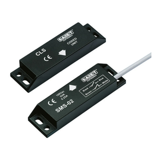
- Page 1 Sensori magnetici SMS Unità magnetiche CLS SMS Magnetic Sensors CLS Magnetic Units Manuale Utente / User Manual...
-
Page 2: Table Of Contents
INDICE / INDEX INTRODUZIONE ........3 FISSAGGIO E DIMENSIONI MECCANICHE ....3 Sensori parallelepipedi . -
Page 3: Introduzione
PArAllelePiPedi magnetica CLS. Per tutti i prodotti, Il fissaggio di SMS e CLS (Fig. 1) è le coppie SMS/CLS di seguito possibile mediante apposite asole descritte costituiscono un sistema laterali del contenitore, adatte a viti codificato ridondante a flusso mul- M4. - Page 4 Fig. 1 - SMS/CLS parallelepipedi Fig. 2 - SMS cilindrici (Esempio) Fig. 3 - CLS cilindrica (Esempio) CLSA3 CLSA2 / CLSA2M...
- Page 5 Fig. 4 - Azionamento e allineamento dei sensori parallelepipedi nibili in contenitore totalmente o gio della unità magnetica è possi- parzialmente filettato nei diametri bile mediante il foro centrale che M18 ed M30; le relative unità permette il passaggio della vite e magnetiche CLS sono disponibili del dado di serraggio.
-
Page 6: Azionamento
Posizionamenti differenti possono modelli. portare alla commutazione di un La codifica dei sensori magnetici solo canale oppure di nessuno dei di sicurezza SMS impone che, per due. azionare ciascun sensore, le corri- Posti SMS e CLS a contatto spondenti unità magnetiche CLS... -
Page 7: Installazione
6 mm tra SMS/CLS e le parti ferro- Accertarsi che conduttori, cavi o magnetiche più prossime della materiali liberi non possano venire macchina. -
Page 8: Controlli Periodici E Manutenzione
SMS + CLS, è di fatto un care che il cablaggio sia corretto e dispositivo la cui elusione è da rite- che il tempo di arresto della mac- nersi difficile. -
Page 9: Dati Tecnici
(SMS/CLS) montati za cavo variata, rispetto allo stan- lontano da parti ferromagnetiche. dard, si identifica con xMT o Inoltre il sensore SMS deve poter xxMT nella parte finale del codice essere attivato frontalmente (vede- (esempio: SMS03 con cavo da 5 re fig. - Page 10 3 2 N.A. Contatti non indipendenti Parametro B10d: 2.5 x 10 cicli di commutazione, con piccoli carichi Tab. 1: Contatti e massima categoria di sicurezza in cui impiegare i sensori SMS Fig. 7: Pin-out CM1A4 Fig. 8: Pin-out CF1A4...
- Page 11 Pin 3-Pin 4: N.C. (Fig. 7) (Segnale) SMS10 1 cavo SMSA2P10 BLU - NERO: N.A. 2x0.35 mm SMSA2M10 SMSA2P30 1 cavo - NERO: N.A. SMSA2P30S2 4x0.15 mm BIANCO - MARRONE : N.A. SMSA3P30 Cavi blU e mArrone collegati internamente Tab. 2: Collegamenti dei sensori SMS...
- Page 12 Peso ca. 70 g ca. 60-90 g M18 x 1 x 38 dado ch.24 Dimensioni SMS (mm) 25 x 88 x 13 M18 x 1 x 50 dado ch.24 M30 x1.5 x 42 dado ch.36 CLSA2: ø25 x 9.3 vite M4...
- Page 13 PaRametRi SmS03nC, SmS03nCS1, SmS03nCS2 Funzione 1 N.C. (Segnale) 2 N.A. (Sicurezza) D-ON (mm) 16 ± 6 20 ± 3 D-OFF (mm) 21 ± 6 22 ± 5 D-RESET (mm) --------- 22 ± 5 V max commutata 100 VCA I max commutata 0.25 A P max commutata 5 VA...
- Page 14 PaRametRi SmS10 SmS10nC SmS10nCCm1 Funzione 1 N.A. 1 N.A. (Sicurezza) + 1 N.C. (Segnale) D-ON (mm) 20 ± 3 20 ± 3 16 ± 6 D-OFF (mm) 22 ± 5 22 ± 5 21 ± 6 D-RESET (mm) 22 ± 5 22 ±...
- Page 15 NOTE In conformità con ISO14119, montare gli interruttori di sicurezza in modo tale che: - Non siano facilmente smontabili (ad esempio uso di viti autobloc- canti, rivetti, ...) - L'accesso da parte degli operatori sia difficoltoso quando la prote- zione è aperta - Siano protetti contro la manomissione o la commutazione involonta- ria.
-
Page 17: Introduction
Type 4 coded sys- ArAllelePiPed SenSorS tem with low-level coding, as The SMS/CLS pairs (Fig. 1) can be defined in the standard ISO mounted using the slots on both 14119:2013. The design of the... - Page 18 Fig. 1 - Parallelepiped SMS/CLS Fig. 2 - Cylindrical SMS (Example) Fig. 3 - Cylindrical CLS (Example) CLSA2 / CLSA2M CLSA3...
-
Page 19: Cylindrical Sensors
Fig. 4 - Operating and alignment direction of the parallelepiped sensors magnetic units mounting is possi- CylindriCAl SenSorS ble through the countersunk hole, The SMS cylindrical sensors are which allows the screw and the nut available in flush or non-flush to pass through it. -
Page 20: Operating Mode
CLS must be carried out: ArAllelePiPed SenSorS The CLS unit must be brought - radially, centering sensor and closer to the SMS sensors so that magnetic unit so that the axes of the printed arrows are faced (see the two cylindrical cases match Fig. -
Page 21: Installation
INSTALLATION the SMS sensors must avoid any possibility for the operator to reach ArningS dangerous parts of the machine. The SMS safety sensor and the The connections of all the SMS relative CLS coded magnetic unit sensors are listed in Table 1; the... -
Page 22: Maintenance
Based on the indication of the - all the operations concerning the standard, a multiple flow coded machine start-up procedure. magnet, such as the SMS + CLS Maintenance consists of a regular systems, is a device difficult to be cleaning of the sensor and the eluded. -
Page 23: Technical Data
1. NOTE. The technical data of this manual TECHNICAL DATA are applicable also to the SMS All the distances involved are models with different cable length. referred to a sample CLS device, The special products, that are... - Page 24 3 2 N.O. these contacts are not independent B10d parameter: 2.5 x 10 switching cycles, with small load Tab. 1: Contacts and maximum safety category to be applied to the SMS sensors Fig. 7: Pin-out CM1A4 Fig. 8: Pin-out CF1A4...
- Page 25 Pin 3 - Pin 4: N.C. (Fig. 7) (Signal) SMS10 1 cable SMSA2P10 BLUE - BLACK: N.O. 2x0.35 mm SMSA2M10 SMSA2P30 1 cable BLUE - BLACK: N.O. SMSA2P30S2 4x0.15 mm WHITE - BROWN : N.O. SMSA3P30 Cables blUe and broWn connected internally Tab. 2: Connections of SMS sensors...
- Page 26 Degree of protection IP67 Operating temperature [-25 ÷ 70] °C Operating/Storage humidity 5 ÷ 95% Misalignment SMS/CLS Max ± 4 mm Max ± 2 mm Weight Ca. 70 g Ca. 60-90 g M18 x 1 x 38 nut ch. 24...
- Page 27 PaRameteRS SmS03nC, SmS03nCS1, SmS03nCS2 Function 1 N.C. (Signal) 2 N.O. (Safety) D-ON (mm) 16 ± 6 20 ± 3 D-OFF (mm) 21 ± 6 22 ± 5 D-RESET (mm) --------- 22 ± 5 V max Switching 100 Vac I max Switching 0.25 A P max Switching 5 VA...
- Page 28 PaRameteRS SmS10 SmS10nC SmS10nCCm1 Function 1 N.O. 1 N.O. (Safety) + 1 N.C. (Signal) D-ON (mm) 20 ± 3 20 ± 3 16 ± 6 D-OFF (mm) 22 ± 5 22 ± 5 21 ± 6 D-RESET (mm) 22 ± 5 22 ±...
- Page 29 NOTES In compliance with ISO14119, fit the safety switches in such a way that: - they are not easily detachable (e.g. use of self-locking screws, rivets, ...) - they are difficult for operators to access when the guard is open - they are protected against tampering or unintentional switching It must be possible to inspect and replace the safety switches, by qualified personnel only.
- Page 30 CaRlo gavazzi si riserva il diritto di apportare modifiche senza preavviso CaRlo gavazzi reserves the right to make changes without prior notice CaRlo gavazzi ContRolS S.p.a. via Safforze, 8 - 32100 belluno, italy tel.+39 0437 355811 – Fax +39 0437 355880...
Need help?
Do you have a question about the SMS and is the answer not in the manual?
Questions and answers