Table of Contents
Advertisement
Quick Links
Advertisement
Table of Contents

Subscribe to Our Youtube Channel
Related Manuals for Venini VCG64


Summary of Contents for Venini VCG64
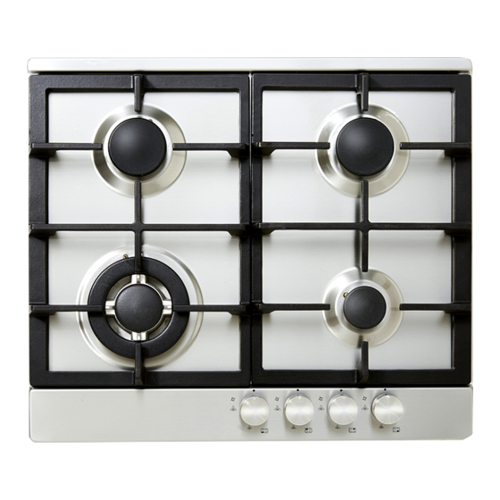
- Page 1 VCG64 60cm Gas Cooktop 2 year warranty venini.com.au...
- Page 2 This manual explains the proper installation and use of your appliance, please read it carefully before using even if you are familiar with the product. The manual should be kept in a safe place for future reference. In case of failure, only the Authorized Technical Service may repair this hob.
-
Page 3: Safety Instructions
The power supply cord (supplied) must not touch Safety Instructions against any hot surfaces and must be placed so Safety When Installation that its temperature does not exceed 75 degrees DO NOT USE OR STORE FLAMMABLE at any point along its length. MATERIALS IN THE APPLIANCE STORAGE After connecting to gas, check for leaks using DRAWER OR NEAR THIS APPLIANCE. - Page 4 Burner Product Description GHS604A-G2CI Pan support Panel knobs Model Burner* Knob Total gas Over supports position consuption view GHS604A-G2CI, 1W+2SR+1A With 2 types for Front LPG: VGC64 option 30.5MJ/h 29.5MJ/h GHS604B-G2CI, 1R+2SR+1A With 2 types for Front LPG: GFC60, VGF60 option 27.5MJ/h 26.0MJ/h...
- Page 5 Accessory Picture Quantity Name ( for reference only, physical unit maybe different) User Manual Sealing tape 1 roll You have additional rating label in accessory bag, suggest Additional 1 set attach it onto a surface where it can be read e.g. inside labels surface of adjacent cupboard Installation...
-
Page 6: Installation
Installation Before Installation: Before cutting into any bench tops, ensure the minimum clearances to walls, adjacent surfaces and overhead surfaces required by the relevant gas appliance installation code (see above) will comply. Dimensions are specified in millimeters (mm) Overhead cupboards and range hood = 650 mm. Side and rear clearance = 200 mm to any burner edge. - Page 7 2. Place Burner Box Apply the adhesive sealing tape to the underside lip of the burner box. Shown at G opposite. Place burner box into cutout hole and fit clamping brackets to clamp the hotplate to the bench. 3. Fit Burners And Trivet. Replace burners and ensure they are correctly repositioned over the ignitor (S) and thermocouple (T).
-
Page 8: Setting The Gas Pressure
After having installed the hotplate, the GPO must always be in an accessible position. Wiring diagram 4. Gas Connection Install in accordance with relevant gas standards and/or codes of practice applicable. Connect the elbow fitting to the appliance gas manifold connection, and check that seals between the elbow and manifold connection are in place and in good condition. -
Page 9: Gas Conversion Instructions
ADJUSTING THE BURNER MINIMUM FLAME HEIGHT: NOTE: This adjustment can only be performed by the installer or an authorised service personnel. The minimum burner flame is factory adjusted for the gas type stated on the gas type label adjacent to the gas connection and should not require adjustment. - Page 10 The hotplates are fitted with mains powered electronic spark ignitors, so must be connected to mains power supply (i.e. nominal 220~240 V ac) to operate. If power is not available, the hotplate will still work but the burners will have to be lit with a match or similar. Depressing the gas control knob of any burner will activate the spark ignition for all burners.
-
Page 11: Stainless Steel
Maintenance & Troubleshooting Cleaning and maintenance should be carried out with the appliance cold especially when cleaning the enameled parts. Avoid leaving alkaline or acid substances(lemon juice, vinegar etc.) on the surfaces. STAINLESS STEEL The stainless steel hob of the hotplate must be cleaned regularly (e.g. -
Page 12: Troubleshooting
TROUBLESHOOTING Servicing of the hotplates must only be done by an authorised service representative (see back of this booklet) and the hotplate must not be modified. Power must be disconnected before any servicing or maintenance is conducted. DO NOT MODIFY THIS APPLIANCE. It is recommended the hotplate serviced by an authorized person at least every 2 years. - Page 13 venini.com.au...
Need help?
Do you have a question about the VCG64 and is the answer not in the manual?
Questions and answers