Table of Contents
Advertisement
Quick Links
REV. 4.0
th
29
May 2012
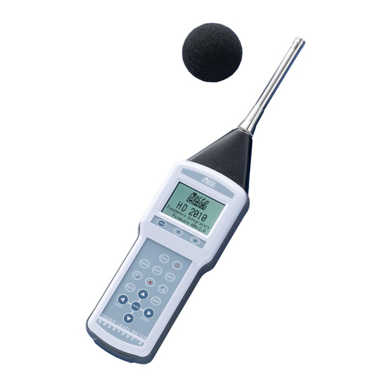
HD2010UC
Integrating Sound Level Meter
ENGLISH
Our instruments' quality level is the results of the product continuous development. This
can bring about differences between the information written in this manual and the instru-
ment that you have purchased. We cannot entirely exclude errors in the manual, for which
we apologize. The data, figures and descriptions contained in this manual cannot be le-
gally asserted. We reserve the right to make changes and corrections without prior notice.
Advertisement
Table of Contents

Related Manuals for DeltaOHM HD2010UC


Summary of Contents for DeltaOHM HD2010UC
- Page 1 REV. 4.0 May 2012 HD2010UC Integrating Sound Level Meter ENGLISH Our instruments' quality level is the results of the product continuous development. This can bring about differences between the information written in this manual and the instru- ment that you have purchased. We cannot entirely exclude errors in the manual, for which we apologize.
- Page 3 1. Microphone. 2. Preamplifier. 3. Preamplifier or extension cable connector. 4. Symbol showing measurement status: RUN, STOP, PAUSE, RECORDING or HOLD. 5. Keypad LEFT key: in graphic mode, it moves the selected cursor towards lower values. 6. Keypad CURSOR key: in graphic mode, it allows to select one or both of the two cursors. 7.
-
Page 4: Connector Function
CONNECTOR FUNCTION The instrument is equipped with five connectors: one in front, one to the side and three at the bot- tom. The figure on page 2 shows: n. 3 - 8-pole DIN connector for preamplifier or extension cable. The connector, located on the instrument front face, has a positioning notch and a screw ring nut to ensure proper lock- ing. - Page 5 Laboratory first line standards at the national metrological institute. Tipo Prodotto: Fonometro Integratore Product Type: Integrating sound level meter HD2010UC Nome Prodotto: Product Name: DELTA OHM SRL 35030 Caselle di Selvazzano (PD) Italy Via Marconi, 5 Tel.
-
Page 6: Introduction
Attention has been paid to the possibility of updating the instrument, and the HD2010UC can be integrated, at any time, with other options like “Advanced Data Logger” to extend its application scope. The firmware can be upgraded directly by the user using the NoiseStudio program supplied with the instrument. - Page 7 (according to UNI9432) measuring the equivalent sound pressure level A weighted with Impulse time constant (LAeqI). The class 1 HD2010UC sound level meter with the “Advanced Data Logger” option is suitable for sound level monitoring and acoustic mapping. Using the “Advanced Data Logger” option, it can also perform assessments of the acoustic climate with capture and analysis of sound events.
- Page 8 scriptors in parallel with reports sequences with 5 dedicate parameters and complete statistical analysis. Moreover, during data logging, the trigger function enables user to identify events recording 5 acoustic parameters together with statistical descriptors of each event. • During recording, up to 9 different markers are available in order to signal the occurrence of particular situations to be considered during the traces analysis phase.
-
Page 9: Hd2010Uc Block Diagrams
HD2010UC B LOCK IAGRAMS The block diagram shows the main elements of the HD2010UC sound level meter. -
Page 10: The Microphone
The UC52 condenser microphone is pre-polarized and has a ½” standard diameter. The fre- quency response in free field is flat from 20Hz to 16kHz for type 1 sound level meter version HD2010UC Kit1 (UC52/1). Version used for type 2 sound level meter version is flat from 25Hz to 10KHz... -
Page 11: The Preamplifier
• HD2010PNE2: connector for ½” UC52 microphone and driver for up to 10m extension cables. This preamplifier, supplied with CTC electric calibration device, can be directly plugged into the HD2010UC sound level meter or connected via extension cable (up to 10mt). • HD2010PNE2W: heated preamplifier with connector for ½” UC52 microphone and driver for extension cables. -
Page 12: The Instrument
NSTRUMENT The signal of the preamplifier comes to the instrument receiver and its output is sent to the LINE connector and to the A/D converter input. The instrument can be set to use the LINE channel in place of the signal coming from the preamplifier. The A/D converts the analogue signal into the numeric format at 20 bits. -
Page 13: Description Of Display Modes
DESCRIPTION OF DISPLAY MODES The HD2010UC measures simultaneously 3 selectable parameters (statistic ones too) and dis- plays them at a fixed frequency corresponding to 2 measurements/s; simultaneously (with “Advanced Data Logger” option) measures the A weighted sound pressure level with FAST time constant and displays it at 8 samples/s;... - Page 14 • HOLD: the calculation of integrated measurements has come to the end of the set integration interval, or HOLD was pressed. • P (Print): indicates that printing is in progress. • M (Monitor): indicates (flashing) that continuous data printing has been started. •...
-
Page 15: Slm ( Sound Level Meter )
SLM ( SOUND LEVEL METER This is the display mode upon power on. Three parameters (selectable among the following ones) can be displayed simultaneously: • Instantaneous acoustic parameters such as L (Short) and L . The instantaneous pressure level is displayed as the maximum level reached every 0.5s. •... -
Page 16: Selecting Parameters
The “analogue bar” shows the unweighted sound pressure instantaneous level in an 80 dB in- terval. Three measuring parameters are displayed under the analogue bar. All displayed parameters can be freely selectable among the available ones. There are no restrictions in the selection of frequency weightings. - Page 17 before pressing PAUSE, for example, because they were caused by unexpected events and not char- acterizing the sound being examined. During measurement, press PAUSE/CONTINUE: integrated measurements update will be in- terrupted. At this point, press the LEFT arrow to delete the last recorded data. The integration time value will be temporarily replaced by the word ERASE followed by the time interval (in seconds) to be deleted.
-
Page 18: Time Profile Mode ( Requires The "Advanced Data Logger " Option )
). The integration time is equal to 1/8s and the last 100 measured samples are displayed. The HD2010UC sound level meter calculates the sound level 128 times a second and displays the maximum level at intervals equal to 125ms. Pressing HOLD, the display update will be stopped; however, the instrument continues meas- uring and pressing HOLD again will restart display updating. -
Page 19: Using The Cursors
The integration mode do not influence this screen recording functioning. The sound level displayed on this screen can be used as source for the event trigger (see para- graph “EVENT TRIGGER FUNCTION” on page 24). SING THE URSORS To activate cursors on the graph, press CURSOR on the keypad. If you press CURSOR re- cursor, or both ΔL cursors in “tracking”... -
Page 20: Graphs
TATISTICAL RAPHS The functioning mode with advanced statistical analyser, available with “Advanced Data logger” installed, allows analyses on the sound pressure level with FAST time constant (sampled 8 times per second) or short equivalent level (integrated every 0.125s) or peak level (calculated twice per second) with any frequency weighting (only C or Z for peak level). -
Page 21: Level Distribution Of Probabilities
The HOLD key does not affect this display mode. When the continuous recording is activated with the single integration mode, the integration time acts like a timer for data acquisition, stopping automatically the measurement when the time is elapsed. When the level integration is performed in multiple mode, the statistical graphs are cleared at the beginning of every interval. -
Page 22: Percentile Levels Graph
the selected cursor will flash. Use the LEFT and RIGHT arrows on the keypad to move the selected cursor on the graph. The second line at the top of the display shows the level and central frequency of the class and the relevant probability indicated by the active cursor, or the probability for the levels in the interval be- tween the two cursors when they are both active. - Page 23 Using the Cursors The CURSOR, LEFT and RIGHT keys on the keypad enable and move the cursor. The second line at the top of the display shows the percentile level indicated by the cursor. Press CURSOR again to disable the cursor.
-
Page 24: Event Trigger Function
EVENT TRIGGER FUNCTION The Event trigger function is available with the “Advanced Data Logger” option and can be enabled only with the single integration mode. During measurement this function can be used to isolate a sound event identifiable by sound level variation or by synchronization to an external sig- nal or, manually, by pressing a key. - Page 25 Per each event identified, 2010UC calculates the following: • 5 programmable selectable parameters: maximum and minimum levels, peak level, equiva- lent level and SEL. • Full statistical analysis These parameters are not displayed but can be stored, completely or partially, at the end of each level.
-
Page 26: Description Of The Different Integration Modes
DESCRIPTION OF THE DIFFERENT INTEGRATION MODES The 2010UC makes measurements according to two different acquisition modes either single (standard for 2010UC) or multiple (“Advanced Data Logger” required). The single integration begins by resetting the integrated levels (e.g. the Leq) and ends when the set integration time Tint is elapsed or when the acquisition is manually interrupted by the RUN/STOP key. -
Page 27: Single Integration
INGLE NTEGRATION When the integration mode is single, the sound level meter resets the integrated parameters (i.e. Leq), starts measuring the instant sound levels (i.e. SPL) and calculates the integrated levels (i.e. Leq, maximum and minimum levels or statistical levels), regularly until acquisition stops. This mode provides, at the end of the measurement session, the integrated levels over the whole acquisition period. -
Page 28: Multiple Integration ( Requires The "Advanced Data Logger " Option )
“MULTI” integration mode prevents the possibility to use the Report Interval parameter to re- cord at defined time intervals and over triggered events. Statistical analysis and integrated levels are zeroed at the beginning of each integration interval. The following table gives the different measurement and storage modes of the HD2010UC. Auto-Store Continuous Recording... -
Page 29: Print And Monitor Functions
PRINT AND MONITOR FUNCTIONS If you press and soon release the PRINT key, you can send to a PC or to a printer, via the serial interface, the screen-page displayed when pressing the key, in ASCII format. The suggested serial printer can be the HD40.1 (please refer to page 66) On the instru- ment display, a letter “P”... -
Page 30: The Record Function
THE RECORD FUNCTION The REC key supervises the function of recording data on the instrument memory. Two recording modes are available: the single (manual or automatic) and continuous recording. The automatic (Auto-Store) and continuous recording modes are available with the “Advanced Data Logger” option”. MANUAL AND AUTOMATIC SINGLE RECORDING When only the REC key is pressed for at least 2 seconds, the displayed screen will be re- corded as a single record. -
Page 31: Continuous Recording
ceded by the reset to zero of integrated levels (ref. to chapter “DESCRIPTION OF THE DIFFERENT INTEGRATION MODES” ). This integration mode, together with Auto-Store function, enables to record, over a time pe- riod equal to the integration time, the parameters available on the SLM mode screen. The integra- tion time (equal to recording time period) is programmable on the SLM mode screen or, alterna- tively, using the specific parameter on the menu (MENU >>... -
Page 32: Continuous Recording Of Report And Events Groups
CONTINUOUS RECORDING OF REPORT AND EVENTS GROUPS With the Advanced Data Logger option, by performing the measurements in single integra- tion mode, you can also record reports and events. The parameters of the SLM and PROFILE screens are included in the Measurement group. Together with the Measurement group recording, you can also enable the Report and Event groups recording. - Page 33 Fig. 10 When the trigger function detects an event, identified by the overcoming of the trigger thresh- old, or when ENTER is pressed, a time marker is recorded. Similarly, when the end of event conditions are sensed, as identified by the deactivation threshold being reached, or by the external TRGIN signal, or when ENTER is pressed, and after the set stop delay has elapsed, another time marker is recorded.
- Page 34 Delayed acquisition timer A timer is available to enable data acquisition according to a programmable delay of up to 99 hours. To perform an acquisition with delayed start, the recording parameters need to be set first and then the delayed acquisition timer programmed in the parameter Menu >> Sequencer >> Timer.
-
Page 35: Description Of The Menu Functions
DESCRIPTION OF THE MENU FUNCTIONS The menu collects all of the parameters through which the instrument functions are set. The menu can be accessed even when the instrument is measuring, but parameters can be modified only if the instrument is in STOP mode. If this is not the case, a message will invite you to stop the current measurement: “WARNING! Stop the measurement to continue". -
Page 36: Instrument
Press MENU to exit a menu and return to the upper level until you get the measurement display again. When you access the menus, current date and time are displayed, as well as the battery charge level and the available memory. If you are in a submenu, the "SELECT MENU"... -
Page 37: Input/Output
(or device) baud rates are the same. Take care of this note when using data transfer programs requiring a manual configuration of the serial port parameters, such as, i.e. HyperTerminal. The NoiseStudio program, combined with the HD2010UC automati- cally sets the serial port, so that no action by the operator is required. -
Page 38: Sound Level Meter
Press RIGHT to change the time weighting of measuring parameters, when selected. When the time weighting flashes, use the UP and DOWN arrows to change it. The list of available parameters is shown on appendix A1. HD2010UC Measuring Parameterson page 98... -
Page 39: Trigger
• Class width: statistical analysis is performed by 0.5dB classes. • Display Stat.: enables (ON) or disables (OFF) displaying of the distribution of probabilities and percentile levels graph. RIGGER The Trigger menu (needs the “Advanced Data Logger” option) collects the specific parameters re- lated to the event trigger. -
Page 40: Report
When this parameter is set to SAV or WME, the sound level meter frequency response is corrected for the windshield or the outdoor shield presence, respectively. The ran- dom incidence correction is not available on the HD2010UC Class 2. For additional details on applied microphone correction, please see UC2 microphone manual. -
Page 41: Sequencer
EQUENCER The Sequencer menu needs the “Advanced Data Logger” option. • Timer: programmable acquisition delay in seconds, minutes, or hours up to a maximum of 99 hours (see paragraph “Delayed acquisition timer ” on page 34). -
Page 42: Programs
PROGRAMS The item PROGRAMS (PROG key) includes the following functions: • Navigator: to display stored data (“Advance Data Logger” required), • Electric and Acoustic Calibration • Diagnostic Check: diagnostic test of instrument, • Data copy on MC: this program allows to copy measurements stored on sound level meter’s flash memory onto an external Secure Digital memory card (please refer to related chapter on page 73). - Page 43 2003/01/01 10 00 00 Batt 95% Mem 92.5% EXIT LOAD NEXT The following data are indicated for each file: the type (single, multiple or automatic), the progressive number given by the instrument upon logging and the date. Press NEXT to jump to the next file, press LOAD to download the current file.
- Page 44 When replaying reports and events, in the SLM screen, reports and events parameters will be dis- played respectively. When events are displayed they are shown one by one, including automatically a pause between the event and the next one. During pause, pressing the START key, allows to load the data of the following event and PAUSE to restart replay.
-
Page 45: Calibration
“warm- up” period necessary every time the instrument is switched on. The HD2010UC sound level meter stores all calibration typical parameters with respective date and time in a reserved area. The calibration types can be: •... - Page 46 ANSI standards (see the parameter of the menu: CALIBRATION >> Microphone Response). The HD2010UC sound level meter is suitable for measurements on site in a temperature range between –10°C to +50°C, in a static pressure range between 65 kPa and 108 kPa and in a relative humidity range between 25% and 90%.
-
Page 47: Periodic Calibration
ERIODIC CALIBRATION The periodic calibration of the HD2010UC sound level meter is needed to ensure the traceability to the laboratory standards and is carried out in accredited laboratories, for example, SIT, etc. The HD2010UC sound level meter is calibrated at Delta Ohm Acoustic Laboratory (SIT laboratory N. - Page 48 Avoid to use the unit in the presence of steam containing oil, conductive or corrosive substan- ces. Also humidity condensation on the membrane must be avoided, as it modifies acoustic re- sponse, causes corrosion and contributes to the formation of residues difficult to remove. When HD WME weather protection is connected and sound level meter turned ON, power supply and preamplifier heating avoid condensation of humidity on the microphone membrane.
-
Page 49: Electric Calibration
LECTRIC CALIBRATION The electric calibration, using the partition of charge injected into the microphone preampli- fier in “charge amplifier” configuration (Capacitive Transducer Calibration), even if it cannot completely replace the acoustic calibra- tion, provides however a useful means to keep under control the instrument drifts, mi- crophone included. - Page 50 5. If you press YES, the calibration is run: wait till the procedure will be over. 6. At the end, the calibration result will be shown and you will be asked to confirm a new cali- bration: ELECTRIC CALIBRATION Last:2003/01/01 10.00 Calibr.
-
Page 51: Acoustic Calibration
1 or class 2 conforming to IEC 60942 and compatible with the microphone capsule UC52 are used. For the HD2010UC models are available Class 1 HD2020 and HD9101calibrators while HD9102 model is available for Class 2 versions. - Page 52 ACOUSTIC CALIBRATION Last:2003/01/01 10.00 Calibr.level 94.0dB 94.0 Turn off the calibra- tor. NEXT 5. After the acoustic calibration, the electric calibration will be automatically started. This stage of the procedure generates the reference data for the following electrical calibrations. ACOUSTIC CALIBRATION ACOUSTIC CALIBRATION Last:2003/01/01 10.00 Last:2003/01/01 10.00...
- Page 53 ACOUSTIC CALIBRATION ACOUSTIC CALIBRATION Last:2003/01/01 10.00 Last:2003/01/01 10.00 Calibr.level 94.0dB Calibr.level 94.0dB -0.1 96.1 Δ Take off the calibrator Checking microphone polarization EXIT 8. Take out the preamplifier from the calibrator and press EXIT. 9. The procedure is over. If calibration constants were incompatible with a correct working of the instrument, calibration would fail and the message “Calibration failed! Consult the manual”...
-
Page 54: Microphone Replacement
The firmware, that is the program managing all of the instrument functions, can be upgraded by transferring the file from a PC to the HD2010UC through the serial/USB port. In this way, all the instrument functions can be updated. Up-dating files are available at the authorized dealers. -
Page 55: Battery Symbol And Battery Replacement
BATTERY SYMBOL AND BATTERY REPLACEMENT The battery symbol in the upper right corner of the display constantly provides the charge status of the instrument batteries. The more the batteries discharge, the more the symbol gets “empty " … ... when the battery voltage reaches the minimum value for a correct operation, the symbol flashes. At this point, only 5 minutes of autonomy are left and batteries should be replaced as soon as possi- ble. -
Page 56: Instrument Storage
WARNING ABOUT THE USE OF BATTERIES • Batteries should be removed when the instrument is not used for an extended time. • Flat batteries must be replaced immediately. • Avoid loss of liquid from batteries. • Use waterproof and good-quality batteries, if possible alkaline. •... -
Page 57: Serial Interface
USB master able to supply with the necessary power and to manage the communication. On the HD2010UC standard kit it is included a serial connection cable; the user can choose between code HD2110RS for PC with COM ports or code HD2110USB for PC with USB ports. - Page 58 The following signals are connected to the 9 pin sub D male connector of the HD2110/RS cable: Direction Signal Description DCE >> HD2010UC DCE - CD DCE ready – Carrier detect DCE >> HD2010UC Receiving data channel HD2010UC >> DCE Transmitting data channel HD2010UC >>...
-
Page 59: Communication Protocol
OMMUNICATION ROTOCOL The command consists of ASCII strings with a variable length, ending in CR-LF. The instrument provides always a response, after a command has been received; if the command is not accepted, the response string is always NAK-CR-LF. It is possible to disable the response, when it is not expressly requested by the command, modifying the VERBOSE setup parameter (see the SET paragraph). -
Page 60: Set Group (Setup)
SET G (SETUP) ROUP The following table shows the list of the commands of the SET group (SETUP). Command Format Description INSTR_MODEL Instrument model - UNMODIFIABLE INSTR_NUMBER Instrument serial number - UNMODIFIABLE INSTR_VERSION Instrument version - UNMODIFIABLE MIC_MODEL Microphone model – UNMODIFIABLE MIC_NUMBER Microphone serial number –... - Page 61 Command Format Description 3_REP_PARAMETER REPORT parameter 3 (see parameter list) 4_REP_PARAMETER REPORT parameter 4 (see parameter list) 5_REP_PARAMETER REPORT parameter 5 (see parameter list) REP_PARAMETERS Recording of REPORT parameters 1-5 (ON/OFF, default: OFF) REP_STATISTICS Statistical recording (ON/OFF, default: OFF) 1_EVN_PARAMETER EVENT parameter 1 (see parameter list) 2_EVN_PARAMETER EVENT parameter 2 (see parameter list)
- Page 62 Parameter Value EVN_TRIGGER MIC_CORR WND_SHL_CORR EVN_PRINT The parameters that can be displayed in SLM mode are selectable among the following ones: Parameter Attribute Description Z or C Instantaneous peak level, Z or C weighted Lpkmx Z or C Peak maximum level LeqS Z, C or A Short equivalent level, Z, C or A weighted...
-
Page 63: Key Group
KEY G ROUP The following table shows the command list of the KEY group. Command Format Description LEFT LEFT key MENU MENU key PRINT PRINT key PROG PROG key PAUSE PAUSE key RUN key SELECT SELECT key UP key MODE MODE key RIGHT RIGHT key... - Page 64 The STT:ACQUISITION commands are provided in the following table Command Format Description HOLD Interrupts display update UPDATE Restarts display update PAUSE Measurement in pause Starts measurements STOP Ends measurements CLEAR Clears measured levels CONTINUE Restarts measuring ERASE Erases the last x seconds of measure- ments RECORD Starts and records measurements...
-
Page 65: Dmp Group (Dump)
The following table lists the STT:RECORDER commands. Command Format Description Starts the Record function Terminates the Record function AUTO Enables the Auto-Store function STT:MONITOR:? and STT:RECORDER:? commands provide information on the monitor and re- cording status as shown in the following example. STT:REC:? STT:RECORDER:Measurement:SLM:OFF DMP G... -
Page 66: Connection To A Modem
PC to the telephone line must not meet any particular requirement, but being Hayes© compatible, the modem connected to the HD2010UC sound level meter has to be configurable by the sound level meter itself and shall not interfere with improper messages during the delicate data transmis- sion phase from the sound level meter to the PC. -
Page 67: Connection To A Printer
3. Parity: None 4. Stop bits: 1. 5. Handshaking: Xon/Xoff 6. Auto feed: Enabled. Connect the HD2010UC sound level meter to the printer by means of the special HD2110/RS ca- ble. Follow the instructions in the documentation supplied with the printer. -
Page 68: Connection To Apc With Usb Interface
ONNECTION TO A WITH INTERFACE The 2010UC sound level meter fitted with USB interface can be connected to a PC’s USB port by using the HD2110/USB cable. The USB port connection requires the previous installation of a driver contained in the Noise Studio software. -
Page 69: Note For Installation
OTE FOR INSTALLATION Note 1: for Windows Vista and Windows 7 operating systems. 1. For software installation is requested Administrator permission 2. If the operating system prevents the software to open, boot the PC as administrator, insert in- stallation CDRom and, when the following window appears, select “Open folder to view files” 3. - Page 70 When USB cable is unplugged, the above items will disappear and they will appear again as soon as the instrument is plugged to USB port. In the documentation supplied with the Noise Studio CDRom, it’s available a detailed version (in- cluding images) of the USB driver management guide.
-
Page 71: Hd2010/Mc Memory Card Reader
HD2010/MC MEMORY CARD READER The memory card reader HD2010/MC can be used on the sound level meters provided with M12 serial connection. If they aren’t provided with M12 input, they can be modified in order to be able to use the memory card reader HD2010/MC. HD2010/MC ESCRIPTION OF THE INTERFACE FOR MEMORY CARD The reader HD2010/MC allows to expand the storage capacity of the sound level meter. -
Page 72: Connection Of Hd2010/Mc To The Sound Level Meter And Use Of The Memory Card
6. When the message “Formatting completed” appears, press OK for confirmation and CLOSE to exit. 7. Close the Noise Studio software. 8. The formatting has been accomplished and the card is ready for use. HD2010/MC ONNECTION OF TO THE SOUND LEVEL METER AND USE OF THE MEMORY CARD Connection of the HD2010/MC: 1. -
Page 73: Reading Data Directly From Pc
For disabling HD2010/MC temporarily: Set the menu item “MENU >> General >> Input/Output >> Serial device” on a different device than MC. In order to re-enable the reader, set the menu item on “MC”. EADING DATA DIRECTLY FROM In order to read and copy files from the memory card to the PC, use a memory card reader for PC: the card will be recognized as external peripheral mass storage device. -
Page 74: Technical Specifications
TECHNICAL SPECIFICATIONS The HD2010UC sound level meter is a type 1 or 2 integrating sound level meter with statistical analysis and optional logging. HD2010UC complies with the following standards IEC 61672:2002-5 Class 1 or Class 2 Group X IEC 60651:2001-10 Class 1 or Class 2 IEC 60804:2000-10 Class 1 or Class 2 ANSI S1.4:1983 Type 1 or Type 2... -
Page 75: Metrological Characteristics
DSP allows obtaining a Class 1 response according to IEC61672:2002. The HD2010UC is also available in the Class 2 version. The frequency response of the microphone depends on the presence of devices like wind- shield HD SAV or all-weather protection unit HD WME. - Page 76 Menu >> Calibration >> Shield >> WME. With this setting applied, HD2010UC sound level meter with HD WME protection, fully com- plies to type 1 specifications according to IEC 61672 standard; in such configuration, when used in vertical position, the sound level meter is able to measure accurately environmental noise from above (0°...
- Page 77 Lower Limit Upper Limit Input Gain [dB] Parameter [dB] [dB] LpkC LpkZ LpkC LpkZ The starting level for the linearity range detection matches the reference level (94 dB) at 1 kHz. With different frequencies, the starting level takes into account the attenuation of the fre- quency weighting being measured.
-
Page 78: Electrical Characteristics
LECTRICAL HARACTERISTICS Pre-heating time Lower than 10 seconds. Power Supply Batteries: 4 alkaline or rechargeable AA 1.5V internal batteries. The sound level meter does not have a battery charger. Autonomy: >12 hours in RUN mode with alkaline good-quality batteries. Amounting to 8 hours when using the outdoor microphone unit HD WME fitted with heated preamplifier. -
Page 79: Statistical Analysis
Serial interface Socket: 8-way M12 Type: RS232C (EIA/TIA574) or USB 1.1 or 2.0 not insulated Baud rate: between 300 and 230400 baud Data bits: 8 Parity: None Stop bits: 1 Flow control: Hardware Cable length: max 15m Extension Cable for the Microphone The microphone preamplifier can be connected to the sound level meter body through an exten- sion cable up to 10m long (CPA). -
Page 80: Storage Of Measurements
TORAGE OF EASUREMENTS The basic version is fitted with a permanent 4 MB memory, corresponding to over 500 single measurements. If “Advanced Data Logger” option is installed the memory capacity can be dou- bled to 8 MB ( “memory module” option). In this case it’s possible to store: Continuous recording mode: almost 24 hours of recording (3 parameters twice per second plus 1 parameter 8 times per second) -
Page 81: Other Characteristics
Firmware To be upgraded via the serial port with NoiseStudio software THER HARACTERISTICS Printing Direct printing of logged parameters (printing of a single event) Continuous Printing (Monitor). Case Dimensions (Length x Width x Height): 445x100x50mm equipped with preamplifier Weight: 740g (batteries included) Materials: ABS, rubber Time Date and time: clock and date updated in real time... -
Page 82: Reference Standards
REFERENCE STANDARDS • IEC 60651:2001, Class 1 or 2. • IEC 60804:2000, Class 1 or 2. • IEC 61672-1:2002, Class 1 or 2 Group X • ANSI S1.4-1983, Type 1 or 2. EMC S TANDARD EGULATIONS • Protection degree IP64 •... -
Page 83: Ordering Codes
ORDERING CODES HD2010UC kit 1: type 1 integrating sound level meter kit with 4MB memory The kit includes the HD2010UC class 1 integrating sound level meter, HD2010PNE2 pream- plifier, UC52/1 free field microphone, microphone extension cable CPA/5, RS232 null- modem serial cable for connection of COM ports (HD2110/RS) or USB (HD2110/USB), HD_SAV windshield, NoiseStudio PC software (basic version), plastic carrying case, instruc- tion manual. - Page 84 Compared to the version “HD2010UC Kit2” also includes: • Heated preamplifier HD2010PN2W with 5mt extension cable (up to 10m on request) • Microphonic outdoor protection HD WME • Calibration certificate according to IEC 60651 and IEC 60804, of the measurement chain...
-
Page 85: Accessories And Spare Parts
the national (D.L. 194/2005 and D.M. 16/03/1998) and EU legislation regarding the acoustic pollution and the mapping of the territory. NS4 “Monitor” module. Acoustic monitoring and PC remote control. Programmed data acquisi- tion, events identification and synchronized audio recording. ACCESSORIES AND SPARE PARTS UC52/1: Type 1 Free Field prepolarized condenser microphone. -
Page 86: What Shall I Do If
EASUREMENT ROCEDURE When the “Advanced Data Logger” option is active, the HD2010UC sound level meter can acquire 3 parameters of SLM screen simultaneously (twice/second), as well as the A weighted sound level with FAST time constant (8 times/second). The available parameters are those listed in the tables of appendix A1, on page 98. -
Page 87: Storage Of Measurements With The "Advanced Data Logger " Option
DVANCED OGGER PTION The HD2010UC, sound level meter, when provided with the “Advanced Data Logger” option, of- fers two different storage modes: 1. The Continuous Recording (press REC and START keys simultaneously) implies the storage of the SLM screen-page (2 samples a second) together with the time profile of the A weighted sound pressure level with FAST constant time (8 samples a second). -
Page 88: Measurement Of Noise Dose
tion mode (MENU >> Instrument >> Measurement >> Integration Mode: MULT) allows to re- cord at intervals equal to the set integration time (MENU >> Instrument >> Measurements >> Integration interval) the data displayed on SLM screen. Set in this way and once the integration time has been reached, the sound level meter will first record data, then set all integrated levels to zero, and finally start a new integration period. -
Page 89: Statistical Analysis
The sound level meter calculates the following parameters: DOSE (A), the percentage of the daily effective dose, and DOSE,d (A), the estimated daily DOSE according to the programmed parame- ters. The DOSE calculation is characterized by three parameters: 1. DOSE Criterion is the SPL constant value, which continuous exposure for 8 hours determines a 100% DOSE. -
Page 90: Troubleshooting
TROUBLESHOOTING The HD2010UC sound level meter is provided with a diagnostic program (DIAGNOSTIC CHECK) that automatically checks the instrument main parameters. This program can be run at any time to check the instrument operating conditions (see description on page 54). -
Page 91: Miscellaneous Problems
Press and hold down the ENTER key while reinserting the battery: the sound level meter will auto- matically turn on. Confirm the load of factory calibration. The sound level meter calibration parameters are restored to the last factory calibration; all menu items are simultaneously brought back to the factory parameters (default). -
Page 92: Keyboard Description
KEYBOARD DESCRIPTION HOLD key The HOLD key can be used to temporarily suspend the display update while the instrument contin- ues making the requested measurements. A “H” in the left corner at the top shows that the display is in this phase. Press the key again to go back to standard measurement. While the instrument is in HOLD mode, you can jump from a screen-page to the other, activate the cursors on the graphic pages, print and store data. - Page 93 MENU key The HD2010UC sound level meter requires, according to its use, many parameters to be set. If you press MENU, you can access all instrument parameters, for the following functions:...
- Page 94 PRINT key Press PRINT to send the screen page to the RS232 serial interface, in a printable format. Data can be downloaded to a PC or sent to a serial printer as for example the HD40.1 (see page 67), directly connected to the sound level meter. In this last case, set the parameter MENU >> Instru- ment >>...
- Page 95 PAUSE/CONTINUE key The PAUSE key interrupts the calculation of integrated measurements (Leq, SEL, maximum or minimum levels, spectra, etc.), as well as recording. The instantaneous levels are still measured and displayed in the SLM screen. Press PAUSE/CONTINUE to start measuring again. The integrated parameters are cleared if you press RUN/STOP/RESET while in PAUSE (during a measurement session).
- Page 96 SELECT key The SELECT key activates the adjustment mode of displayed parameters by selecting them in se- quence. Use the two arrows, UP and DOWN, to modify the values. When you have finished with the adjustments, wait a few seconds or press ENTER to confirm and quit the selection mode. UP key The UP key selects a previous line in the menus or increases the selected parameter.
- Page 97 rows, or press MENU. Factory setup is loaded into the sound level meter by turning it on while holding the ENTER key. RIGHT key The RIGHT key selects the next character in the active line of the menu. It jumps to the next pa- rameter during the selection of a measuring variable that needs the definition of more than one pa- rameter (see SELECT).
-
Page 98: Annex
ANNEX A1. HD2010UC M EASURING ARAMETERS In the next paragraphs, are shown the acoustic parameters that can be displayed in numeric or graphic format, with the respective abbreviations used to identify them. ACOUSTIC DESCRIPTORS (NUMERIC DISPLAY) Instantaneous acoustic levels refreshed every 0.5s Wideband WEIGH. - Page 99 COUSTIC LEVELS GRAPHIC DISPLAY Time Profile (with “Advanced Data Logger” option) Wideband Levels WEIGH. WEIGH. PARAMETER ABBREV. DEFINITION FREQ. TEMP. Sound pressure maximum level (SPL LFmx AFmax (SPL Statistical Analysis WEIGH. WEIGH. PARAMETER ABBREV. DEFINITION FREQ. TEMP. Peak level X=Z, C LXpk Equivalent level X=Z, C, A...
- Page 100 WEIGH. WEIGH. PARAMETER ABBREV. DEFINITION FREQ. TEMP. Sound pressure minimum level (SPL X=Z, C Event group acoustic descriptors (with “Advanced Data Logger” option) 5 selected parameters WEIGH. PARAMETER ABBREV. DEFINITION WEIGH. FREQ. TEMP. Equivalent continuous level X=Z, C, A LYmx Sound pressure maximum level (SPL X=Z, C, A Y=F, S, I...
-
Page 101: A2. Memory Capacity During The Logging Function
UNCTION With the supplied 4 MB memory you can store up to 500 recordings. Through the “Advanced Data Logger” option, the HD2010UC can automatically store data accord- ing to two different modes: continuous and automatic recording. The sound level meter storage capacity when in Continuous Recording mode is equal to 23 hours with the supplied memory of 4 MB. -
Page 102: A3: The Sound
A3: T OUND The sound is a variation of pressure audible by the human ear. Its propagation, starting from the source, occurs in the form of waves and is thus subject to all the phenomena typical of the waves, such as refraction and diffraction. The propagation speed depends on the medium and, in the air, at ambient temperature, it equals to about 344 m/s. - Page 103 Noises characterized by the presence of a pure tone, are more bothering, at the same level, with respect to noises distributed over a wide interval of frequencies. The reason is to be found in the sound energy “concentration” in the ear mechanics. Usually, the sound level is not static, but it changes with time.
-
Page 104: A4: Sound Level Meter
A4: S OUND EVEL ETER The sound level meter is the instrument that measures the sound level. Usually, it is made up by a microphone, the sound sensitive element, by an amplifier, by a signal processing unit and by a reading and data display unit. -
Page 105: Time Constants And Exponential Weighting
gram” where the sound levels are represented in graphic format for each of the bands in which the sound spectrum has been divided. IME CONSTANTS AND EXPONENTIAL WEIGHTING Further processing of the microphone signal is needed when fluctuating sound levels have to be measured. -
Page 106: Equivalent Sound Pressure Level
In case a sound source emits noises with a strong impulsive component, the level measured with the IMPULSE constant will be much higher than the SLOW level. The figure shows the sound level profile, measured simultaneously using the FAST, SLOW, and IMPULSE time constant by a sur- face mount machine. -
Page 107: Statistical Analysis
This is particularly important in assessing the impact of the sound produced by machines or general pollution sources on the auditory apparatus. It is obvious that a strong noise generates a growing damage proportional to exposure. Evaluation of potentially harmful noise is therefore easy with constant level sounds. - Page 108 for each class is calculated by dividing the sampling frequency by the total number of samples. The result is the sound level distribution of probabilities shown below. After this, the cumulative distribution is calculated. This is based on the sound level distribu- tion of probabilities, beginning with a 100% probability for all lower classes with a value lower than the minimum measured level and for each class progressively subtracting the corresponding distribution probability of the level probabilities.
-
Page 109: Noise Dose
OISE The measurement of the “Dose” of noise is used in the field of noise monitoring in a working environment, meant as a percentage fraction of a maximum daily exposure to noise. The organiza- tions taking care of safety in working environments have defined some standards for the measure- ment of the noise dose considering the energy content of sound pressure and comparing it with a maximum daily equivalent level (over an 8-hour time interval) that is, in Italy, equal to 85 dBA (A weighted equivalent level) when no hearing protection is available. -
Page 110: Environmental Influence
Humidity The HD2010UC sound level meter and the microphone are not affected by relative humidity up to 90%. However, protect the microphone from rain and snow and keep it clean. In case of bad weather, it is suggested to use a windshield and, in case of use in very humid environments, the proper microphone dehumidifier should be applied. -
Page 111: Classification Of Acoustic Signals
of the sound level meter in conditions of high humidity with consequent condensation, can cause damages. • Check the battery level of both sound level meter and calibrator. • Check that the sound level meter is calibrated by measuring the calibrator reference sound level. This inspection has to be repeated at the end of measurements to assure the sound level meter stability. - Page 112 Non-stationary signals have sound levels depending both on the period of measurement and on in- tegration time. The time taken for the analysis is critical for this type of acoustic signals and the fre- quency analysis has to measure all levels in every band of the spectrum at the same time. The ana- lyzer suitable to this kind of measurement is called to operate in “real time”.
-
Page 113: A5. Microphone Outdoor
A5. M HD WME - ICROPHONE UTDOOR ROTECTION ASSEMBLY DISASSEMBLY AND MAINTENANCE Are given below operating instructions to disassembly, assembly and periodic maintenance of HD WME outdoor protection unit. A5.1 - Disassembly To completely disassemble the unit, a 1.5mm male hex key and a 14mm wrench are needed. To separate all components of the unit, proceed as follows;... - Page 114 3. Unscrew the terminal placed at the lower end of the stern (A). 4. Unscrew the stern (B) and disconnect the cable connected to the preamplifier. 5. Unscrew the lock nut of the preamplifier (C) using, if required, a 14mm wrench. Be careful not to twist the preamplifier cable.
- Page 115 For details on calibration, see the specific chapter at page 40. 7. For assembly of HD WME protection, proceed as described in the next paragraph. A5.2 - Assembly To assemble the unit, a 1.5mm male hex key and a 14mm wrench are needed. To assemble completely the protection, start from step 1.
- Page 116 2. Insert the wind screen HD SAV3. HD SAV3 3. Apply the anti-bird spike and secure it using the three hex head screws located on the support at the base of the windscreen.
- Page 117 4. Insert the preamplifier (A) into the support pushing slowly upward until it’s limit position. 5. Screw the gland (B) using, if necessary, a 14mm wrench. Be careful not to twist the preamplifier cable.
- Page 118 6. Insert the cable connected to the preamplifier through the system (C) and screw the stern to the support. 7. Screw the terminal placed at the lower end of the stern (D) releasing the cable laterally.
- Page 119 8. To secure the outdoor protection you can use the threaded end (D) or you can apply the fitting (E) on the tripod. The terminal (E) has two threads , ½ “ and ¼”.
-
Page 120: A6: Definitions
DEFINITIONS Frequency: is the number of oscillations per second, expressed in Hertz (Hz). Wave Length: is the distance between two adjacent maximum values of pressure, expressed in me- ters (m). Period: is the interval of time necessary to make a complete oscillation, expressed in seconds (s). Sound Propagation Speed: is the distance covered by the sound wave front in the unit of time, ex- pressed in meters/second (m/s). - Page 121 Sound Pressure Level with Frequency Weighting: The sound pressure level can be weighted in frequency applying a filter that changes in a predetermined way the signal spectral structure. Acous- tic standard filters are referred to as A and C. Sound Pressure Level with Time Weighting: The sound pressure level can be exponentially weighted over the time with a given time constant.
- Page 122 Total L calculated by measuring partial L If you need to get the total L after measuring partial L , you can use the formula: ∑ ⋅ ⋅ ∑ where Example: Let’s suppose we measured: = 80 dB over 1 h. eq,1 = 90 dB over 2 h.
- Page 123 Sound Exposure Level: represented by the L symbol (or SEL), it is defined over a given t1 ÷ t2 time interval like: ⎛ ⎞ ⎜ ⎟ ∫ ⋅ ⋅ ⎜ ⎟ ⋅ ⎝ ⎠ where: T = t is the time interval under examination. (t) = the square of instantaneous pressure.
-
Page 124: Table Of Contents
TABLE OF CONTENTS CONNECTOR FUNCTION ............................4 INTRODUCTION ................................6 HD2010UC Block Diagrams ............................ 9 The Microphone ..............................10 The Outdoor Microphone Unit HD WME ....................... 10 The Preamplifier ..............................11 The Instrument ................................ 12 DESCRIPTION OF DISPLAY MODES ........................13 SLM ( ) ............................ - Page 125 ............................90 ESTORING ACTORY ETUP ..........................90 ESTORING ACTORY ALIBRATION ............................91 ISCELLANEOUS ROBLEMS KEYBOARD DESCRIPTION............................92 ANNEX .................................... 98 A1. HD2010UC M ........................ 98 EASURING ARAMETERS A2. M ..................101 EMORY APACITY URING OGGING UNCTION A3: T ................................. 102...
- Page 126 Spectral Analysis ..............................104 Time constants and exponential weighting ......................105 Impulsive Noises ..............................105 Equivalent Sound Pressure Level .......................... 106 Statistical Analysis ..............................107 Noise Dose ................................109 Acoustic Field ............................... 109 Environmental influence ............................110 Precautions and General rules of use ........................110 Classification of acoustic signals ..........................
- Page 128 This guarantee must be sent together with the instrument to our service centre. IMPORTANT: Guarantee is valid only if coupon has been correctly filled in all details. Instrument Code: HD2010UC Serial number RENEWALS Date...
Need help?
Do you have a question about the HD2010UC and is the answer not in the manual?
Questions and answers