Table of Contents
Advertisement
Quick Links
TP32MTT.03 - TP32MTT.03.1
TP32MTT.03 - TP32MTT.03.1
TP32MTT.03 - TP32MTT.03.1
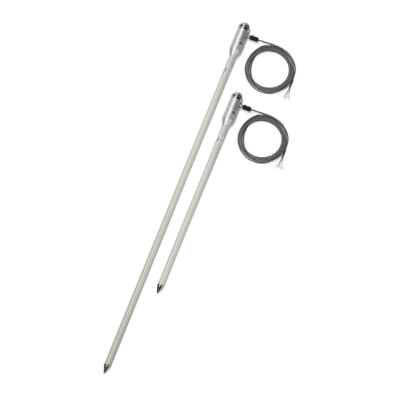
PROBES FOR SOIL THERMAL PROFILE MEASUREMENT
The temperature probe TP32MTT.03 is equipped with seven Pt100 1/3 DIN
sensors for the measurement of temperature at depth: +5 cm, 0, -5 cm, -10
cm, -20 cm, -50 cm, -1 m with respect to the soil level, according to the
indications of the World Meteorological Organization (WMO).
The probe TP32MTT.03.1 is equipped with six Pt100 1/3 DIN sensors for the
measurement of temperature at depth: +5 cm, 0, -5 cm, -10 cm, -20 cm, -50
cm with respect to the soil level.
The fibreglass tube ensures a perfect impermeability and a high thermal
insolation along the vertical axis.
The RS485 digital output with MODBUS RTU protocol allows the use of
even very long connection cables. It can be connected to the datalogger
HD32MT.1 and HD32MT.3, or to any other datalogger with RS485 MODBUS
RTU input.
The M12 connector present on the hand grip of the probe allows an easy
connection of the cable. Cable length (optional) 2, 5 or 10 m, with open
wires at the end.
Power supply 6...30 Vdc.
TECHNICAL SPECIFICATIONS
Sensors
Pt100 1/3 DIN
Resolution
0.01 °C
Accuracy
± 0.1 °C @ 0 °C
Working temperature
Stem: -40...-125 °C
Hand grip: -40...+85 °C
Temperature drift
0.003 %/°C @ 20 °C
Power supply
6...30 Vdc
Consumption
5 mA @ 12 Vdc
Output
RS485 with MODBUS-RTU protocol
Connection
8-pole M12 male connector
Cable
Optional, with 8 poles with length of 2, 5 or 10 m (to
be defined at the order) with open wires at the end.
Protection Degree
IP 68
Fig. 1: dimensions of the probe TP32MTT.03 (mm)
INSTALLATION
By means of an accessory, perform a hole into the soil deep enough to
accommodate the stem of the probe. Never use the probe to make the
hole in the soil, to avoid mechanical damage to the probe itself.
Once the hole has been performed in the soil, insert the stem of the probe
so that the indicator of the zero level is in correspondence with the surface
of the soil. The probe must be stable in a vertical position.
After the introduction of the probe into the hole, fill in the empty spaces
between the soil and the stem of the probe with some soil made powder.
To obtain accurate measurements, the soil should be in contact with the
stem.
Groove to apply the flag
indicating placememt position
Soil level indication on the
Soil level indication on the
stem of the probe
stem of the probe
Soil level
Soil level
Indicate the presence of the probe during the maintenance operations of
the soil (e.g. lawn mowing, ploughing, mechanized harvesting, etc.).
To remove the probe from the soil, insert a pin into the Ø 8mm hole at the
top of the handle and pull it upwards. Remove the probe vertically, avoiding
its inclination during extraction to avoid damaging the stem.
Connect the M12 connector as shown in Fig 3 and 4.
On request, 5 or 10 m standard cables with 8-pole M12 female connector
are available (other lengths available on request).
Probe M12 male
connector
Connector
Function
numbering
1
Negative power supply
2
Positive power supply
3
Not connected
4
RS485 A/-
5
RS485 B/+
6
Not connected
7
Not connected
8
Not connected
Hole Ø 8mm for the introduction of a
Hole Ø 8mm for the introduction of a
pin for the extraction of the probe
pin for the extraction of the probe
Fig. 2: installation
Cable CPM12-8P...
Colour
Black
Red
Brown
White
Fig. 3: connections
Advertisement
Table of Contents

Related Manuals for DeltaOHM TP32MTT.03


Summary of Contents for DeltaOHM TP32MTT.03
- Page 1 World Meteorological Organization (WMO). Indicate the presence of the probe during the maintenance operations of The probe TP32MTT.03.1 is equipped with six Pt100 1/3 DIN sensors for the the soil (e.g. lawn mowing, ploughing, mechanized harvesting, etc.).
- Page 2 PROCEDURE FOR SETTING THE PARAMETERS: Other sensors with RS485 output Start while the sensor is not powered (if the CP24 cable is used, PLC, datalogger or Termination Termination disconnect one end of the cable). converter RS485/USB or RS485/RS232 for PC Start a serial communication program, HyperTerminal for example.
- Page 3 ORDERING CODES OPERATING MODE TP32MTT.03: Temperature probe equipped with seven Pt100 1/3 DIN The probe enters RS485 MODBUS-RTU mode after 10 seconds from power on. During the first 10 seconds from power on, the probe does not respond to any sensors for the measurement of temperature at depth: +5 cm, 0, -5 request from the MODBUS master unit.
Need help?
Do you have a question about the TP32MTT.03 and is the answer not in the manual?
Questions and answers