DeZurik G Series Manual
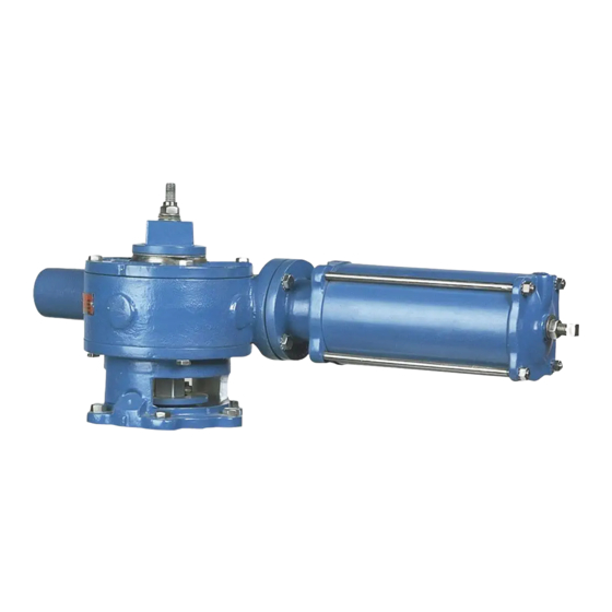
Cylinder operated actuator
Hide thumbs
Also See for G Series:
- Instruction (19 pages) ,
- Manual (17 pages) ,
- Instructions manual (13 pages)

Subscribe to Our Youtube Channel
Related Manuals for DeZurik G Series


Summary of Contents for DeZurik G Series
- Page 1 DEZURIK CYLINDER OPERATED G-SERIES ACTUATOR USED ON PEF 100% PORT ECCENTRIC VALVES D10455 Instruction August 2012 DeZURIK, Inc. Sartell, Minnesota USA | Phone: 320-259-2000 | www.dezurik.com | info@dezurik.com...
- Page 2 Recommended spare parts are listed on the assembly drawing. These parts should be stocked to minimize downtime. Order parts from your local DeZURIK sales representative, or directly from DeZURIK. When ordering parts, please include the 7-digit part number and 4-digit revision number (example: 9999999R000) located on the data plate attached to the valve assembly.
-
Page 3: Table Of Contents
DeZURIK Cylinder Operated G-Series Actuator Table of Contents Description - - - - - - - - - - - - - - - - - - - - - - - - - - - - - - - - - - - - - - - - - - - - - - - - - - - - -... -
Page 4: Description
DeZURIK Cylinder Operated G-Series Actuator Description The G-Series Cylinder Actuator is a totally enclosed, quarter turn, pneumatic operated actuator. Air Supply The supply pressure to the cylinder should be between 50 and 100 psi (344 and 689 kPa). Lubrication The G-Series Cylinder Actuator has been lubricated at the factory and requires no routine lubrication. If the... -
Page 5: Adjusting Position Stops
DeZURIK Cylinder Operated G-Series Actuator Actuator Identification (Continued) Table A: Cylinder Identification “A” Cylinder 10.5 Adjusting Position Stops The G-Series Cylinder Actuators have both open and closed position stops. See Figure 2 for position stop identification. Figure 2 – Position Stops The position stops are factory set and do not require adjustment unless the actuator has been disassembled or actuator orientation has been changed. -
Page 6: Adjusting The Closed Position Stop
DeZURIK Cylinder Operated G-Series Actuator Adjusting Position Stops (Continued) Adjusting Closed Position Stop On 6A and 12A cylinder actuators, the Closed Position Stop is located in the end of the cylinder. See Figure 2. The cylinder must be mounted before adjusting the position stop. - Page 7 DeZURIK Cylinder Operated G-Series Actuator Adjusting Position Stops (Continued) Table B: Cylinder Closing Pressure - Reverse Pressure Drop* Cylinder Closing Pressure Actuator (For Direct Pressure Drop Use Same as 25# Reverse) Valve Size & Cylinder G6-C4 3” (80mm) G6-C6 G6-C4 4"...
-
Page 8: Removing Actuator
DeZURIK Cylinder Operated G-Series Actuator Removing Actuator When eccentric valves are mounted in a vertical pipeline, or mounted in a horizontal pipeline with the plug stem horizontal, gravity can cause the plug to swing to a lower position in the valve body when the actuator is removed. -
Page 9: Removing Cylinder
DeZURIK Cylinder Operated G-Series Actuator Removing Cylinder This procedure can be performed with the actuator installed on the valve or removed. 1. Discontinue flow and relieve pipeline pressure. 2. Apply air pressure to the port in the cylinder cap (the end farthest from the actuator housing) until the valve has moved to the end of its stroke. -
Page 10: Disassembling Actuator
DeZURIK Cylinder Operated G-Series Actuator Disassembling Actuator When eccentric valves are mounted in a vertical pipeline, or mounted in a horizontal pipeline with the plug stem horizontal, gravity can cause the plug to swing to a lower position in the valve body when the actuator is removed. - Page 11 DeZURIK Cylinder Operated G-Series Actuator Disassembling Actuator (Continued) Figure 6 – Actuator Parts Identification August 2012 Page 11 D10455...
-
Page 12: Reassembling Actuator
DeZURIK Cylinder Operated G-Series Actuator Reassembling Actuator Install new bearings (B12) if required and O-rings (B14) in the housing (B1) and cover (B2) if necessary. See Figure 7 for proper placement. Figure 7 – Bearing and O-ring Locations 1. Scrape old gasket material from the housing (B1), cover (B2) and stop cap (B29). - Page 13 DeZURIK Cylinder Operated G-Series Actuator Reassembling Actuator (Continued) Figure 8 – Gear and Rack Alignment 7. Place a new gasket (B26) on the cylinder head. 8. Install the cylinder/rack rod assembly by sliding the rack rod through the rack (B4) and fasten the cylinder to the housing (B1) with screws (B27).
- Page 14 DeZURIK Cylinder Operated G-Series Actuator Reassembling Actuator (Continued) Table C: Spring Washer Arrangement Valve Size Actuator Direct Reverse Size Pressure Pressure 10. Screw the cap nut (B25) onto the rack rod (B6) and tighten the two nuts against each other.
-
Page 15: Changing Mounting Positions
DeZURIK Cylinder Operated G-Series Actuator Changing Mounting Positions The actuator can be mounted in 90 increments around the valve shaft. 1. Discontinue flow, relieve pipeline pressure and close valve. Accidental operation of power actuator can cause personal injury or equipment damage. - Page 16 If you use metric fasteners with ASME Class 150/300 bolt holes and flange bolt patterns, you do so at your sole risk and any liability associated with such use shall not be the responsibility of DeZURIK, Inc. In addition to the foregoing, DeZURIK’s Manufacturer’s Conditions apply.
Need help?
Do you have a question about the G Series and is the answer not in the manual?
Questions and answers