Table of Contents
Advertisement
Quick Links
Advertisement
Table of Contents

Related Manuals for DeZurik POWERRAC R1


Summary of Contents for DeZurik POWERRAC R1
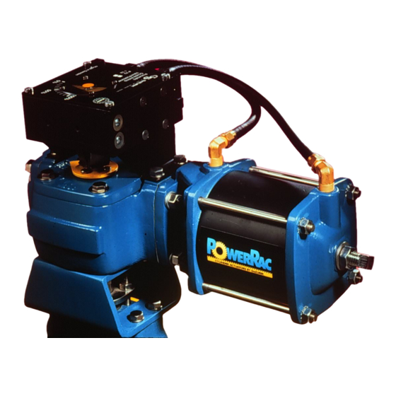
- Page 1 DeZURIK R1 AND R2 POWERRAC™ ACTUATORS D10268 Instruction July 2016...
- Page 2 Recommended spare parts are listed on the assembly drawing. These parts should be stocked to minimize downtime. Order parts from your DeZURIK sales representative, or directly from DeZURIK. When ordering parts, please include the 7-digit part number and 4-digit revision number (example: 9999999R000) located on the data plate attached to the valve assembly.
-
Page 3: Table Of Contents
DeZURIK R1 and R2 POWERRAC™ Actuators Table of Contents Description ..........................4 Installation ..........................4 Operation ........................... 5 Lubrication ..........................6 Position Stops ..........................7 Removing Actuator ........................8 Actuator Disassembly ......................... 8 Double-Acting Cylinder Disassembly ..................10 Spring-Return Cylinder Disassembly..................11 Spring-Return Cylinder Reassembly .................. -
Page 4: Description
The cylinder mounting interface is the same for all PowerRac™ actuators. A lockable model of The DeZURIK PowerRac™ actuator is also available. Operation of the lockable model is described on page 19. -
Page 5: Operation
DeZURIK R1 and R2 POWERRAC™ Actuators Installation (continued) Figure 1—R1 and R2 PowerRac™ Configurations Operation The R1 and R2 PowerRac™ actuator is powered pneumatically, and rotates 90° between the open and closed positions, in the direction as described above. The double-acting cylinder is sized for 60 psi or 80 psi (415 kPa or 550 kPa), and the spring-return cylinder is sized for a 60 psi (415 kPa) spring only. -
Page 6: Lubrication
DeZURIK R1 and R2 POWERRAC™ Actuators Lubrication The actuator has been lubricated at the factory and requires no routine lubrication. If the actuator is disassembled (see Figures 2 thru 4 for actuator parts identification); apply a paint-like coating using one of these lubricants: - Dow Corning Molykote No. -
Page 7: Position Stops
DeZURIK R1 and R2 POWERRAC™ Actuators Position Stops The adjustable open and closed position stops prevent the actuator from rotating beyond the open and closed positions of the valve. Double Acting Actuator The closed position stop is located in the cylinder cap, and the open position stop is located in the actuator end cover. -
Page 8: Removing Actuator
DeZURIK R1 and R2 POWERRAC™ Actuators Removing Actuator Refer to Figure 2 for component identification. Flow in the pipeline with the actuator removed can allow the valve to slam closed and cause personal injury and/or damage to the flow system. Shut down the flow in the pipeline before removing the actuator from the valve. - Page 9 DeZURIK R1 and R2 POWERRAC™ Actuators Actuator Disassembly (continued) Figure 2—Actuator Assembly, Less Cylinders July 2016 Page 9 D10268...
-
Page 10: Double-Acting Cylinder Disassembly
DeZURIK R1 and R2 POWERRAC™ Actuators Double-Acting Cylinder Disassembly Refer to Figure 3 for component identification. 1. Remove the tie rod nuts (C15) and washers (C13) from the tie rods (C12). 2. Remove the cylinder cap (C11). 3. Push the piston rod (C4) through the cylinder head (C1), and remove the piston (C7) and piston rod (C4). -
Page 11: Spring-Return Cylinder Disassembly
DeZURIK R1 and R2 POWERRAC™ Actuators Spring-Return Cylinder Disassembly Refer to Figure 4 for component identification. The spring assembly (S19) contains a compressed spring that can cause death or personal injury if the cylinder tie rod nuts are removed while the spring force is on the tie rod nuts. -
Page 12: Spring-Return Cylinder Reassembly
DeZURIK R1 and R2 POWERRAC™ Actuators Spring-Return Cylinder Reassembly Clean and inspect all parts before reassembly. Refer to Figure 4 for component identification. See Figure 1 for orientation of cylinder assembly and end cover on spring-to-open and spring-to-close actuator configurations. See “Lubrication” section for lubricating requirements. -
Page 13: Double-Acting Cylinder Reassembly
DeZURIK R1 and R2 POWERRAC™ Actuators Spring-Return Cylinder Reassembly (continued) 4. Tighten the nut to 45 ± 5 foot pounds (61 ± 7 Nm). 5. Place the O-ring (S8) in the smaller groove of the piston (S7). Place the piston seal (S9) in the larger groove of the piston as far around the circumference as possible without stretching the seal. -
Page 14: Double-Acting Actuator Reassembly
DeZURIK R1 and R2 POWERRAC™ Actuators Double-Acting Cylinder Reassembly (continued) 6. Place the piston rod seal (S3) in the cylinder head (S1). 7. Push the piston rod (S4) through the cylinder head (S1) so that the piston (S7) is against the cylinder head. - Page 15 DeZURIK R1 and R2 POWERRAC™ Actuators Double-Acting Actuator Reassembly (continued) 6. With the four tapped holes facing upwards, place the gear (B8) into the housing bearing (B2), and engage the gear teeth with the rack (B5) following the procedure applicable to your configuration: •...
- Page 16 DeZURIK R1 and R2 POWERRAC™ Actuators Double-Acting Actuator Reassembly (continued) Figure 5 —Collet Assembly and Gear Alignment 7. Place the O-ring (B10) in the groove of the top cover (B11). 8. Mount the top cover (B11) and gasket (B13) to the housing (B1) with the four screws (B15) and washers (B14).
- Page 17 DeZURIK R1 and R2 POWERRAC™ Actuators Double-Acting Actuator Reassembly (continued) 10. tighten the rack screw (B7): • On the R1 model, tighten the screw (3/8") to 44 foot pounds minimum (60 Nm) • On the R2 model, tighten screw (1/2") to 108 foot pounds minimum (147 Nm) 11.
-
Page 18: Spring-Return Actuator Reassembly
DeZURIK R1 and R2 POWERRAC™ Actuators Spring-Return Actuator Reassembly Clean and inspect all parts before reassembly. Refer to Figure 4 for component identification. See “Lubrication” section for lubricating requirements. 1. Replace worn parts, especially sealing components such as O-rings and gaskets. - Page 19 DeZURIK R1 and R2 POWERRAC™ Actuators Spring-Return Actuator Reassembly (continued) 7. Place the O-ring (B10) in the groove of the top cover (B11). Figure 6 —Collet Assembly and Gear Alignment 8. Mount the top cover (B11) and gasket (B13) to the housing (B1) with the four screws (B15) and washers (B14).
-
Page 20: Mounting Actuator
DeZURIK R1 and R2 POWERRAC™ Actuators Spring-Return Actuator Reassembly (continued) 11. Turn the jam nut (B22) onto the stop screw (B21), and turn the stop screw into the center hole in the end cover (B17) until the end of the stop screw protrudes about 1/4" (6 mm) through the end cover. - Page 21 DeZURIK R1 and R2 POWERRAC™ Actuators Mounting Actuator (continued) 6. Lubricate the top cover O-ring (B10) and groove in top cover (B11) as described in “Lubrication” section on page 6. 7. Apply a paint like coating of grease as specified in “Lubrication” section on page 6, the both flat sides of the collet wedges (B9B) and to the mating surfaces inside the gear (B8).
-
Page 22: Changing From Double-Acting To Spring-Return Spring-To-Close
DeZURIK R1 and R2 POWERRAC™ Actuators 19. Operate the actuator and valve three full cycles to demonstrate that the unit operates smoothly in both directions. Do not exceed 100 psi (690 kPa) in cylinder(s). Changing from Double-Acting to Spring-Return Spring-to-Close 1. - Page 23 DeZURIK R1 and R2 POWERRAC™ Actuators Changing from Double-Acting to Spring-Return Spring-to-Open (continued) 9. Mount the double-acting cylinder assembly and gasket (B16) to the studs from which the end cover was removed. Place the nuts (B20) and lockwashers (B19) on the studs. Tighten the nuts to 26 ±...
-
Page 24: Changing From Spring-Return Spring-To-Close To Double-Acting
DeZURIK R1 and R2 POWERRAC™ Actuators Changing from Spring-Return Spring-to-Close to Double-Acting 1. Relieve the cylinder pressure, if any, to the actuator. 2. Remove the four cylinder assembly nuts (B20) and lockwashers (B19), and remove the spring- return cylinder assembly (S00) and gasket (B16). -
Page 25: Lockable Model
R1 and R2 POWERRAC™ Actuators Lockable Model The double-acting and spring-return DeZURIK PowerRacTM R1 and R2 Actuators are each available as a lockable model that allows the actuator to be locked in either the open or closed position. The lockable model is identified by PRL in the catalog characteristic. -
Page 26: Locked Open Position
DeZURIK R1 and R2 POWERRAC™ Actuators Lockable Model (continued) Locked Open Position Follow the steps below to change the unit from the unlocked condition to the locked open position. Refer to Figure 7 for component identification. Before proceeding, the open and closed position stops must be correctly adjusted as described in the Open and Closed Stops section. - Page 27 DeZURIK R1 and R2 POWERRAC™ Actuators Lockable Model (continued) Figure 7 – Lockable Model Component Identification July 2016 Page 27 D10268...
-
Page 28: Troubleshooting
DeZURIK R1 and R2 POWERRAC™ Actuators Troubleshooting Condition Possible Cause Corrective Action Actuator closes to wrong Closed position stop is set Adjust closed position stop. position. incorrectly. See Position Stops section. Actuator opens to wrong Open position stop is set Adjust open position stop.
Need help?
Do you have a question about the POWERRAC R1 and is the answer not in the manual?
Questions and answers