DeZurik G Series Instruction
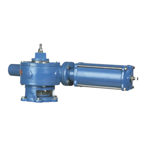
Cylinder operated actuator used on pec eccentric valves
Hide thumbs
Also See for G Series:
- Manual (17 pages) ,
- Instructions manual (13 pages) ,
- Instruction (7 pages)

Related Manuals for DeZurik G Series


Summary of Contents for DeZurik G Series
- Page 1 DEZURIK CYLINDER OPERATED G-SERIES ACTUATOR USED ON PEC ECCENTRIC VALVES D10022 Instruction August 2012 DeZURIK, Inc. Sartell, Minnesota USA | Phone: 320-259-2000 | www.dezurik.com | info@dezurik.com...
- Page 2 Recommended spare parts are listed on the assembly drawing. These parts should be stocked to minimize downtime. Order parts from your local DeZURIK sales representative, or directly from DeZURIK. When ordering parts, please include the 7-digit part number and 4-digit revision number (example: 9999999R000) located on the data plate attached to the valve assembly.
-
Page 3: Table Of Contents
DeZURIK Cylinder Operated G-Series Actuator Table of Contents Description - - - - - - - - - - - - - - - - - - - - - - - - - - - - - - - - - - - - - - - - - - - - - - - - - - - - -... -
Page 4: Description
DeZURIK Cylinder Operated G-Series Actuator Description The G-Series Cylinder Actuator is a totally enclosed, quarter turn, pneumatic operated actuator. A 2" (50mm) square nut on top of the actuator is provided for manual operation. It is supplied with a single cylinder, and single or double booster cylinders dependent on application. -
Page 5: Adjusting Position Stops
DeZURIK Cylinder Operated G-Series Actuator Adjusting Position Stops The G-Series Cylinder Actuators have both open and closed position stops. See Figure 2 for position stop identification. Figure 2 – Position Stops The position stops are factory set and do not require adjustment unless the actuator has been disassembled or actuator orientation has been changed. -
Page 6: Adjusting The Closed Position Stop
DeZURIK Cylinder Operated G-Series Actuator Adjusting Position Stops (Continued) Adjusting Closed Position Stop On actuators without booster cylinders, the closed position stop is located in the end of the cylinder. On actuators with booster cylinders, the closed position stop is located in the end of the booster cylinder. - Page 7 C10B12 * Reverse Pressure Drop: The pressures specified for reverse pressure drop will provide tight pressure shutoff or minimum leakage with maximum plug life. If a dead-tight shutoff with reverse pressure is required, contact DeZURIK August 2012 Page 7 D10022...
- Page 8 — * Reverse Pressure Drop: The pressures specified for reverse pressure drop will provide tight pressure shutoff or minimum leakage with maximum plug life. If a dead-tight shutoff with reverse pressure is required, contact DeZURIK D10022 Page 8 August 2012...
-
Page 9: Removing Actuator
DeZURIK Cylinder Operated G-Series Actuator Removing Actuator When eccentric valves are mounted in a vertical pipeline, or mounted in a horizontal pipeline with the plug stem horizontal, gravity can cause the plug to swing to a lower position in the valve body when the actuator is removed. -
Page 10: Installing Actuator
DeZURIK Cylinder Operated G-Series Actuator Removing Actuator (Continued) This valve is a pressure vessel. On 4, 5, 6 and 10" (100, 125, 150 and 250mm) valves, the same bolts hold both the actuator and the bonnet. Removing the bolts on 4, 5, 6 and 10" (100, 125, 150 and 250mm) valves before relieving pipeline pressure can result in personal injury or equipment damage. -
Page 11: Removing Cylinder
DeZURIK Cylinder Operated G-Series Actuator Removing Cylinder This procedure can be performed with the actuator installed on the valve or removed. 1. Discontinue flow and relieve pipeline pressure. 2. Apply air pressure to the port in the cylinder cap (the end farthest from the actuator housing) until the valve has moved to the end of its stroke. - Page 12 DeZURIK Cylinder Operated G-Series Actuator Installing Cylinder (Continued) Table E: Rack Rod Spring Washer Arrangement Valve Size Direct Reverse Actuator Size Pressure Pressure G16-C8 G16-C10 G16-C12 G16-C10B10 G16-C10B12 G16-C12B12 G16-C12B10B10 G16-C12B12B12 G16-C8 G16-C10 G16-C12 G16-C10B10 G16-C10B12 G16-C12B12 G16-C12B10B10 G16-C12B12B12 G16-C10B12...
-
Page 13: Disassembling Actuator
DeZURIK Cylinder Operated G-Series Actuator Disassembling Actuator When eccentric valves are mounted in a vertical pipeline, or mounted in a horizontal pipeline with the plug stem horizontal, gravity can cause the plug to swing to a lower position in the valve body when the actuator is removed. -
Page 14: Reassembling Actuator
DeZURIK Cylinder Operated G-Series Actuator Disassembling Actuator (Continued) 13. Remove the rack bearing (if noticeable wear to bearing) by driving the pin out of the rack bearing and actuator housing. 14. Scribe corresponding lines on the valve and adapter to be used for alignment during actuator reassembly. - Page 15 DeZURIK Cylinder Operated G-Series Actuator Reassembling Actuator (Continued) 1. Scrape old gasket material from the actuator housing and the adapter, install a new gasket, then fasten the adapter to the actuator housing with the screws. 2. Line up the scribe marks on the valve and adapter made during actuator removal, then set the adapter and housing on the valve.
-
Page 16: Changing Mounting Positions
DeZURIK Cylinder Operated G-Series Actuator Changing Mounting Positions On 4–20" (100–500mm) valves, the actuator can be mounted in 30° increments around the valve shaft. 30° position changes require changing the timing between the gear sector and the rack; 60° position changes do not require changing the timing. -
Page 17: Mounting Actuator In 45° Increments On 24-36" (600-900Mm) Valves Only
DeZURIK Cylinder Operated G-Series Actuator Changing Mounting Positions (Continued) Remove the screws fastening the adapter to the valve. On the 4, 5, 6 and 10" (100, 125, 150 and 250mm) valves, these screws also hold the bonnet to the valve body. -
Page 18: Troubleshooting
DeZURIK Cylinder Operated G-Series Actuator Changing Mounting Positions (Continued) 5. Remove the four screws that hold the wrenching nut to the gear sector, then remove the stud locknut, spring washers and the wrenching nut with the keys. 6. Scribe corresponding lines on the actuator cover and housing, then remove the cover screws and cover from the top of the actuator. - Page 19 If you use metric fasteners with ASME Class 150/300 bolt holes and flange bolt patterns, you do so at your sole risk and any liability associated with such use shall not be the responsibility of DeZURIK, Inc. In addition to the foregoing, DeZURIK’s Manufacturer’s Conditions apply.
Need help?
Do you have a question about the G Series and is the answer not in the manual?
Questions and answers