
Related Manuals for peerless-AV XTREME XHB553


Summary of Contents for peerless-AV XTREME XHB553
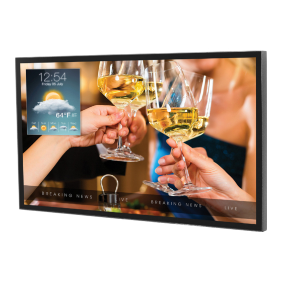
- Page 1 User Guide XTREME HIGH BRIGHT OUTDOOR DISPLAY ™ 2020-11-13 #:180-9149-6 (2021-11-02)
-
Page 2: System Installation And Electrical Requirements
SYSTEM INSTALLATION AND ELECTRICAL REQUIREMENTS Electrical Code Note: To the display system installer: This reminder is provided to call attention to Article 820-44 of the National Electric Code that provides guidelines for proper grounding and, in particular, specifies that the cable ground shall be connected to the grounding system of the facility. Outlet shall be installed near the equipment and shall be easily accessible. -
Page 3: Fcc Caution
Record your display's model and serial number here for future reference. Keep this user manual in an accessible location in the event service is required. Note: Your display's serial number can be found on the box, underneath the rear cover plate, and in the Setup Menu under Peerless-AV Technical Support. Model Number ____________________________________ Serial Number ____________________________________... -
Page 4: General Safety Precautions
GENERAL SAFETY PRECAUTIONS Read before operating equipment Thank you for purchasing our product. Before using it, please read this user guide carefully and follow the instructions for safe operation. Please keep this manual for future reference and always include it when transferring or transporting this product to a different location. - Page 5 • Do not install in enclosure or recessed cavity with less than 2 inches of airflow around the display. Air inside fully encased display must be ventilated. Installations within any third party enclosure without written authorization from Peerless-AV are not covered by the Peerless-AV Limited Warranty, nor any extended warranty.
-
Page 6: Table Of Contents
CONTENTS System Installation and Electrical Requirements ..................2 Electrical Code ..........................2 Power Source ..........................2 FCC Caution ...........................3 FCC Statement ..........................3 Relevant Information ........................3 General Safety Precautions ........................4 Set Up Instructions ..........................7 Parts List ............................7 Removing Cord Cover ........................8 Installing Power Cord ........................9 Installing IR Extender ........................9 Installing ALS Extender ........................9 Installing IR Repeater ........................9... -
Page 7: Set Up Instructions
SET UP INSTRUCTIONS Parts List A ( 1 ) Description A display display B remote C IR extender D regional power cord E 3mm allen wrench cable tie G user guide (not shown) H technical support insert (not shown) mounting caution insert (not shown) B ( 1 ) C ( 1 ) E ( 1 ) -
Page 8: Removing Cord Cover
Removing Cord Cover Remove two M5 low-profile hex screws and rear cover plate using 3mm allen wrench. Do not disconnect lanyard. Remove six M5 hex screws and cord cover using 3mm allen wrench. lanyard CAUTION Do not remove lanyard that connects the rear cover plate to the display. -
Page 9: Installing Power Cord
Installing Power Cord Insert female end of power cord into power port located inside the input compartment. Installing Ambient Light Sensor Installing IR Extender (Optional) Extender (Optional) Insert the 3.5mm end of the included 5V Insert the 3.5mm end of the Ambient IR extender into the IR Extender port on Light Sensor Extender (ACCD-ALS sold the input panel of the display. -
Page 10: Connecting Cords
Supports Network Control and Monitoring* 15 12V DC Output Supplies 12V DC, 2.5A 16 5V DC Output Supplies 5V DC, 2.4A 17 AC Input Supports 100 ~ 240V, 50/60Hz / Region-Specific Power Cord *Visit www.peerless-AV.com product page to download Monitoring Instructions. 2020-11-13 #:180-9149-6 (2021-11-02) -
Page 11: Replacing Cord Cover
Replacing Cord Cover Run power and signal cords through separate cable channels to prevent unwanted interference. Route the power cord through the right most cable channel. (see image 1 below). Replace the cord cover ensuring the cords are running through the cable channels and not getting pinched. -
Page 12: Removing Handles
Removing Handles (Optional) Do not remove. CAUTION Do not remove the screws above or below the handles. Failure to follow these instructions can result in the product being damaged or destroyed, voiding the warranty. Connect to the Power Source Connect power cord to GFCI outlet. 2020-11-13 #:180-9149-6 (2021-11-02) -
Page 13: Prepare The Display For Mounting
Install cords prior to mounting your display. Input panel may be obstructed once the display is mounted. A mounting solution is sold separately. Contact your Peerless-AV representative for an outdoor rated mounting solution for your particular application. For your safety, only install an outdoor-rated mount that is suitable for the application and supports the weight of the display. - Page 14 Prepare the Display for Mounting Display 50.07" 29.24" 47.62" 26.79" 54.64" 0.49" 55" (1272mm) (743mm) (1210mm) (680mm) (1388mm) (12mm) FRONT VIEW 1.58" (40mm) 1.24" (31mm) .79" (20mm) 1.24" (31mm) BEZEL / IR DETAIL VIEW 2020-11-13 #:180-9149-6 (2021-11-02)
-
Page 15: Remote Control Battery Installation And Replacement
Incorrect usage of batteries can result in leaks of the battery module. Slide the battery or bursting. Peerless-AV recommends the module out of the remote control. following battery use: Insert two new “AAA” size batteries into •... -
Page 16: Operating Instructions
OPERATING INSTRUCTIONS Power On/Off the Display Power on your display using the remote control or the power button on the bottom, right-hand side of the display. The display will power on but image may not appear for several seconds as it completes its power up sequence. -
Page 17: Navigating The On-Screen Menu
Navigating the On-Screen Menu Picture Picture Mode Standard Dynamic Allows the user to alter the Brightness, Contrast, Soft Color, and Sharpness of the video image to User better match the look of the video against the environment it’s being viewed in. Color Temperature Normal Warm... -
Page 18: Audio
Navigating the On-Screen Menu Audio Sound Mode Standard Music Allows the user to tailor the Treble and Bass Movie frequency output of the Analog headphone jack. User Note: These setting do not affect the TOSLink output (digital audio). Balance: Default = 0 (centered) Alters the Left and Right speaker output. -
Page 19: Time
Navigating the On-Screen Menu Time Sleep Timer 60 min 5 min 90 min Allows the user to set a predetermined 10 min 120 min time for the display to power down. 15 min 180 min 30 min 240 min Daylight Savings Time On / Off Allows the user to set the TV to switch for Daylight Savings Time. -
Page 20: Setup
Navigating the On-Screen Menu Setup Menu Languages English / Spanish / French / German / Italian / Russian Allows the user to set the default language of the OSD. Transparent 100% Allows the user to set the transparency of the OSD Menu. - Page 21 Navigating the On-Screen Menu Setup Backlight ECO Mode Min / Middle / Max / ALS / Personal Backlight / Custom Schedule Allows the user to use a predetermined preset, custom preset, Ambient Light Sensor or a custom backlight schedule for the overall brightness of the display.
- Page 22 Allows the user to get a visual readout of the sensors with the display that are used for monitoring the health and wellness (Sensor Information can be viewed through the web page). Peerless-AV Technical Support (Information Only) Allows the user to see model number, serial number, and firmware revision.
-
Page 23: Lock
Navigating the On-Screen Menu Lock Enter Password Default PIN = 0000 Set Password (User Defined) 4 Digit numeric combination Allows user to change the PIN for security. Safety Lock On Power On Only Power Toggle Allows the user to set the external power button Button Lock to a fixed command. -
Page 24: Media Functionality
Media Functionality Insert USB flash drive into USB 2.0 Data Select media source to access content. port on the input panel of the display. Input Source HDMI1 HDMI2 Media USB 2.0 Data TV/SPK EXIT EXIT EXIT MENU EXIT MENU MENU •... - Page 25 Media Functionality Select media type and folder where content is stored. PHOTO MUSIC MOVIE TEXT PHOTO MUSIC MOVIE TEXT Return Return Photos – To view a single photo, Movies – To view a single video, select photo and press play. To view select video and press play.
-
Page 26: (Rs-232C) Serial Control Of The Display
(RS-232C) Serial Control of the Display Attach an RS-232C cable (straight through type) to the supplied D-Sub RS-232C to utilize serial control function. Control via RS232 should only be utilized by experts familiar with RS232 programing. (0): A0, F0, 55, FF, 56, A9 Left: A0, F0, 55, FF, 0C, F3 (1):... -
Page 27: Maintenance
MAINTENANCE Care of the Screen Do not rub or strike the screen with anything hard as this may scratch, mark, or damage the screen permanently. Ensure that the display is installed in a location where it will be safe from abrasives and flying debris, which could damage the LCD panel. -
Page 28: Warranty
Garantia TÜR Garanti̇ Garanzia Záruka www.peerless-av.com/warranty Peerless-AV Peerless-AV Europe Peerless-AV América Latina 2300 White Oak Circle Unit 3 Watford Interchange, Av. de las Industrias 413 Aurora, IL 60502 Colonial Way, Watford, Herts, Parque Industrial Escobedo Email: tech@peerlessmounts.com WD24 4WP, United Kingdom General Escobedo N.L., México 66062...