Table of Contents
Advertisement
Quick Links
Advertisement
Table of Contents

Related Manuals for Surface Concept HVPS


Summary of Contents for Surface Concept HVPS
- Page 1 19“ HVPS Detector Supply 1 Channel (Release R020) Manual...
- Page 2 User Manual for the 19” HVPS Detector Supply 1 Channel phone: +49 6131 62716 0 Release: R020 fax: +49 6131 62716 29 Manual Version 2.0 email: info@surface-concept.de web: www.surface-concept.de Printed on 2020-11-13 19” HVPS Detector Supply R020 Manual | Surface Concept GmbH...
-
Page 3: Table Of Contents
4.2 General Device Operation ................... 10 4.3 Operation of a MCP/CEM Detector ................11 4.4 Schematic Layout of the 19” HVPS Detector Supply R020 ......12 5 List of Figure ........................... 13 19” HVPS Detector Supply R020 Manual | Surface Concept GmbH... - Page 4 19” HVPS Detector Supply R020 Manual | Surface Concept GmbH...
-
Page 5: Introduction
2.1 General Information This manual is intended to assist users in the installation, operation and maintenance of Release Version 020 of the 19” HVPS Detector Supply. It is divided into 5 chapters. 2.2 Safety Instructions Please read this manual carefully before performing any electrical or electronic operations and strictly follow the safety rules given within this manual. -
Page 6: General Overview
Surface Concept 19” Basic Unit, a modular supply system. The 19” HVPS Detector Supply R020 is laid out for the operation of e.g. MCP based detectors with metal anode or CEM detectors. It provides one single high voltage with a positive polarity. It also provides the capability to float on an external reference potential. -
Page 7: Introduction
The general connection scheme of the 19” HVPS-HC Module R020 is as follows: Figure 1: Connection scheme of the 19” HVPS Detector Supply R020 (the detector flange is given for illustration only. Please check the manual of your MCP/CEM detector for the correct flange layout and feedthrough assignment). - Page 8 • Install the 19” HVPS Detector Supply R020 into a free slot of the 19” Basic Unit (if not already installed). • High voltage output is provided to the SHV socket named “MCP-B”. • The socket named “MCP-F” connects the external reference voltage which is given to the device via the “HV Ref.
-
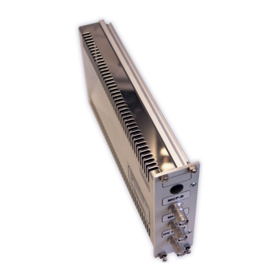
Page 9: Device Layout & Operation
Figure 2: Layout of the 19” HVPS Detector Supply R020. The 19” HVPS Detector Supply R020 is specified for the operation with an external reference voltage of maximum +/- 1,000 V (see no. 3 in Figure 2). Please also respect the corresponding specifications for the maximum voltage for the MCP front potential of your MCP/CEM detector (see the manual and the specification sheet of your MCP/CEM detector for further details). -
Page 10: General Device Operation
After switching on the 19” Basic Unit, its display shows the “Surface Concept” animated logo, while the device is scanning for the 19” HVPS Detector Supply R020 and its specific settings. This can take up to several seconds. If the 19” Basic Unit is ready for operation, it switches into the standby mode and shows... -
Page 11: Operation Of A Mcp/Cem Detector
Application case 2: The detector should be operated with the MCP front side connected to +1000V. In this case the external reference voltage is connected to the “HV Ref. In” input. First set the 19” HVPS Detector Supply R020 to the detectors operation voltage. Then increase the external reference voltage to the +1,000V. -
Page 12: Schematic Layout Of The 19" Hvps Detector Supply R020
4.4 Schematic Layout of the 19” HVPS Detector Supply R020 Figure 6 shows the schematic layout of the 19” HVPS Detector Supply R020 and especially the layout of the HV outputs. An internal controller measures the output voltage and regulates it to the nominal value entered by the user or set as default value within the device. -
Page 13: List Of Figure
Manual 19“ HVPS Detector Supply R020 5 List of Figure Figure 1: Connection scheme of the 19” HVPS Detector Supply R020 (the detector flange is given for illustration only. Please check the manual of your MCP/CEM detector for the correct flange layout and feedthrough assignment).. - Page 14 This declaration does not represent a commitment to features or capabilities of the instrument. The safety notes and regulations given in the product related documentation must be observed at all times. 19” HVPS Detector Supply R020 Manual | Surface Concept GmbH...
Need help?
Do you have a question about the HVPS and is the answer not in the manual?
Questions and answers