Table of Contents
Advertisement
Quick Links
Advertisement
Table of Contents

Related Manuals for Surface Concept MCPD18


Summary of Contents for Surface Concept MCPD18
- Page 1 MCPD18 R104 1-channel MCP Detector MCPD18 (Release 104) Manual...
- Page 2 MCPD18 R104 All rights reserved. No part of this manual may be reproduced without the prior permission of Surface Concept GmbH. Surface Concept GmbH Am Sägewerk 23a 55124 Mainz Germany Tel. ++49 6131 627160 Fax: ++49 6131 6271629 www.surface-concept.com, support@surface-concept.de...
-
Page 3: Table Of Contents
3 Installation..........................................6 3.1 Initial Inspection......................................6 3.2 Installation........................................6 3.2.1 Mounting the MCPD detector..............................6 3.2.2 Cabling and High Voltage................................7 4 Operation of the MCPD18...................................8 4.1 Getting Started......................................8 4.1.1 “Start Up” Procedure..................................8 4.1.2 Dark Count Rate Measurement..............................9 4.1.3 Standard Detector Measurement............................9 4.2 Standard Operation Procedure..............................10 4.3 Bake Out Procedure....................................10... -
Page 4: Introduction
It is divided into 8 chapters. The chapter “Introduction” contains a brief description of the Detector. The chapter “Installation” refers to installation and cabling. Chapter “Operation of the MCPD18” describes the operation of the detector. The final chapters contain amongst others technical details about the microchannel plates and the MCP detector. -
Page 5: General Overview Of The System
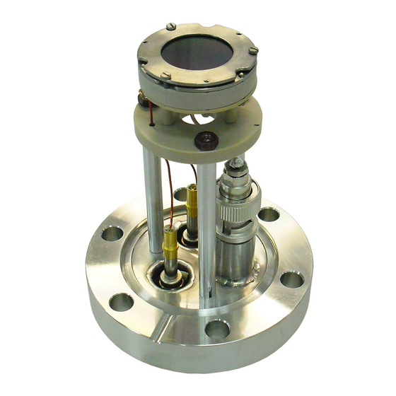
MCPD18 R104 2.3 General Overview of the System The Surface Concept MCPD18 R104 is a 1-channel MCP detector. It consist of a chevron microchannel plate stack and a detector anode. MCP pulses are capacitively coupled into the anode. The anode is a 50Ohm matched system and signal readout is realized ground close via a... -
Page 6: Installation
MCPD18 R104 Installation 3.1 Initial Inspection Visual inspection of the MCPD18 is required to ensure that no damage has occurred during shipping. Should there be any signs of damage, please contact SURFACE CONCEPT immediately. 3.2 Installation 3.2.1 Mounting the MCPD detector The detector is packed under vacuum. -
Page 7: Cabling And High Voltage
MCPD18 R104 3.2.2 Cabling and High Voltage The general connection scheme of the detector is shown in Figure 1. Figure 1: Connection scheme of the MCPD18 R104 “ The detector holds two SHV connectors (labeled MCP-B” and “MCP-F”) for the high voltage supply and one BNC connector (labeled “SIG”) for the signal output. -
Page 8: Operation Of The Mcpd18
If sparking occurs, turn down the high voltage immediately and wait some time (up to 5 min.). Start the “Start-Up” procedure again with an increased ramp time. Turn off the high voltage completely, stop the procedure and call SURFACE CONCEPT for further assistance, if is it not possible to reach the operation voltage without sparking. -
Page 9: Dark Count Rate Measurement
MCPD18 R104 Figure 2: Schematic sketch on voltage ramping during “Start-Up” procedure. The detector starting operation voltage for “MCP-B” is given in the specification sheet. Example: The “MPC-B” voltage is given in respect to the “MCP-F” voltage. A ramp time of 4min. should be used to change the “MPC-B”... -
Page 10: Standard Operation Procedure
If sparking occurs, turn down the high voltage immediately and wait some time (up to 5min.). Start the “Start-Up” procedure again with an increased ramp time. Turn off the high voltage completely, stop the procedure and call SURFACE CONCEPT for further assistance, if is it not possible to reach the operation voltage without sparking. - Page 11 MCPD18 R104 Do not remove the blankets until the entire system has thoroughly cooled off. Do not operate the detector before the temperature has returned to ambient conditions.
-
Page 12: Mcp Detector Layout
5.1 MCPD18 - Vacuum Wiring The MCP detector MCPD18 consist of a detection area, defined by the MCP holders and the detector anode. The front side of the detector anode is on high voltage potential, while the signal readout is realized close to ground potential (in respect to the high voltage of the MCPs). - Page 13 MCPD18 R104 Figure 4: Internal connection of the high voltage potentials (schematic) for the R104. The resistance between “MCP-F” and “MPC-B” (resistance of MCP stack and internal resistor) should be in the range of 100 – 400 MΩ (the exact values are given in the specification sheet of the detector).
-
Page 14: Microchannel Plate
MCPD18 R104 Microchannel Plate 6.1 Specifications Please check the specification sheet of the MCPD for the exact MCP specification. 6.2 Storage Because of their structure and the nature of the materials used in manufacture, care must be taken when handling or operating MCPs. The following precautions are strongly recommended: The most effective long-term storage environment for an MCP is an oil-free vacuum. -
Page 15: Operation
MCPD18 R104 Voltages must not be applied to the device while at atmospheric pressure. The pressure should be 1E-6mbar or lower at the microchannel plate before applying voltage. Otherwise, damaging ion feedback or electrical breakdown will occur. 6.4 Operation A dry-pumped or well-trapped/diffusion-pumped operating environment is desirable. A poor vacuum environment will most likely shorten MCP life or change MCP operating characteristics. - Page 16 MCPD18 R104 Figure 5: Typical gain degradation of MCPs as function of the extracted output charge After an initial burn-in period, in which the detector gain changes as a result of electron induced chemical allocation together with degassing residual gas molecules from the inside of the channels, the MCP performance is very stable over a large amount of extracted output charge.
- Page 17 MCPD18 R104 It is not unusual that the operation voltage must be increased several times especially in the first year of operation. Typically, the final operation voltage at the end of the burn-in period will be close to the recommended maximum operation voltage.
-
Page 18: Mcp Degase Procedure
MCPD18 R104 operation time of the MCPs is an inhomogeneous irradiation of the MCPs. This is connected to a locally (strong) different gain degradation, which results in an inhomogeneous detector response. Locally different gains can still be compensated by increasing the operation voltage, but very often the increasing voltage step must be much larger to reach again a homogeneous detector response. -
Page 19: Technical Data
MCPD18 R104 Technical Data MCPD18 R104: Active area: 18mm Operation voltage at detector: see specification sheet Voltage at MCP front: see specification sheet HV connections: 2 SHV connectors (MCP front, MCP back) Connections for signal: 1 BNC connector (50Ohm matched coaxial signal) Max. -
Page 20: List Of Figure
MCPD18 R104 List of Figure Figure 1: Connection scheme of the MCPD18 R104..........................7 Figure 2: Schematic sketch on voltage ramping during “Start-Up” procedure...............9 Figure 3: Layout of the HV connections and photos of the single detector elements.............12 Figure 4: Internal connection of the high voltage potentials (schematic) for the R104..........13 Figure 5: Typical gain degradation of MCPs as function of the extracted output charge..........16...
Need help?
Do you have a question about the MCPD18 and is the answer not in the manual?
Questions and answers