
Related Manuals for Surface Concept DLD8080


Summary of Contents for Surface Concept DLD8080
- Page 1 DLD8080 R4.30 & R4.31 Manual Delayline Detector DLD8080 (Release 4.30 & 4.31) Manual...
- Page 2 Am Sägewerk 23a 55124 Mainz Germany Delayline Detector DLD8080 phone: +49 6131 62716 0 Release: R4.30 & R4.31 fax: +49 6131 62716 29 Manual Version 2.2 email: info@surface-concept.de Printed on 2019-08-16 web: www.surface-concept.de DLD8080 R4.30 & R4.31 Manual | Surface Concept GmbH...
-
Page 3: Table Of Contents
5.2.2 3D(x, y, t) Time Resolved Imaging .................... 20 5.3 Data Acquisition ............................21 5.4 Working with the DLD - Important Details ..................21 5.5 MCP Outgassing during Operation ....................23 DLD8080 R4.30 & R4.31 Manual | Surface Concept GmbH... - Page 4 8.4 Operation ..............................29 8.5 MCP Lifetime and Operation Voltage ....................29 8.6 MCP Degase Procedure ........................... 32 8.7 Replacement ............................... 32 9 Troubleshooting ..............................33 10 Technical Data ..............................34 11 List of Figure ..............................35 DLD8080 R4.30 & R4.31 Manual | Surface Concept GmbH...
- Page 5 DLD8080 R4.30 & R4.31 Manual DLD8080 R4.30 & R4.31 Manual | Surface Concept GmbH...
-
Page 6: Introduction
This manual is intended to assist users in the installation, operation and maintenance of Release Version 4.30 & 4.31 of the Delayline Detectors DLD8080. It is divided into 11 chapters. The chapter “Introduction” contains a brief description of the DLD. The chapter “Installation” refers to installation and cabling, while the chapter “Principle of Operation”... -
Page 7: General Overview Of The System
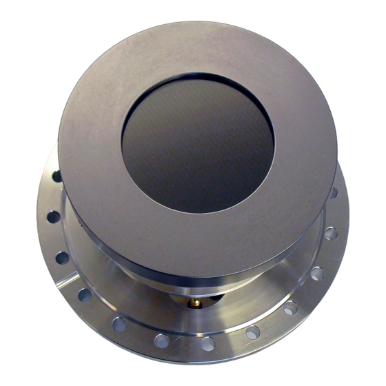
3D(x,y,t) area and time detection of electrons, ions, x-ray and UV-light. The DLD8080 R4.30 & R4.31 are mounted on a CF160 vacuum flange with feedthroughs for high voltage supply and signal transfer. They consist of a microchannel plate stack and two layers (x, y) of meander structured delaylines. -
Page 8: Installation
1 x DLD Readout Cable (HDMI) with Strain Relief • CD with Documentation and Software Table 1: Packing list for the DLD8080 R4.30 & R4.31 Detector. 3.2 Installation 3.2.1 Mounting the Delayline Detector The detector is transported under vacuum. Proceed as follows, to install the detector into your vacuum chamber: •... -
Page 9: Detector Orientation
Figure 1: 0/0 position of the DLD image (black dot). 3.2.3 Cabling and High Voltage • The general connection scheme of the Delayline Detector including its readout package is shown in Figure DLD8080 R4.30 & R4.31 Manual | Surface Concept GmbH... - Page 10 • Use the SHV cables to connect the corresponding outputs of the high voltage power supply (“MCP-F”, “MCP-B”, and “U_DLD”) to the corresponding feedthroughs of the detector. DLD8080 R4.30 & R4.31 Manual | Surface Concept GmbH...
-
Page 11: Software Interface And Installation
Software Installation Manual. Read-out of the delayline detector is done via the USB port of the TDC (time-to-digital-converter). The specific PC system requirements can be found in the corresponding TDC manual. DLD8080 R4.30 & R4.31 Manual | Surface Concept GmbH... -
Page 12: Operation Of The Dld
• Watch the vacuum pressure while increasing the high voltage; turn the voltages back, if an unusual increase is observed in the pressure (indicator for high voltage sparking). DLD8080 R4.30 & R4.31 Manual | Surface Concept GmbH... - Page 13 The voltage for “U_DLD” should be kept fixed at + 400V in relation to “MCP-B” . The voltage for “MCP-B” is always given in reference to the MCP front voltage “MCP-F”. (The Surface Concept HV Power Supply keeps the relation between “MCP-B” and “U_ Note DLD”...
-
Page 14: Dark Count Rate Measurement
Keep in mind the description about the important operation details in Chapter Note Turn off the high voltage, close the software and turn off the TDC before performing any changes of the cabling. DLD8080 R4.30 & R4.31 Manual | Surface Concept GmbH... -
Page 15: Standard Operation Procedure
Keep in mind the description about the important operation details in Chapter Note Turn off the high voltage, close the software and turn off the TDC before performing any changes of the cabling. DLD8080 R4.30 & R4.31 Manual | Surface Concept GmbH... -
Page 16: Operation Of The Detector With The Mcp Front Side Connected To A Reference Voltage16
Start the “Start-Up” procedure again with an increased ramp time. Turn off the high voltage completely, stop the procedure and call your provider for further assistance, if is it not possible to reach the operation voltage without sparking. DLD8080 R4.30 & R4.31 Manual | Surface Concept GmbH... - Page 17 The voltage for “U_DLD” should be kept fixed at +400V in relation to “MCP-B” . The voltage for “MCP-B” is always given in reference to the MCP front voltage “MCP-F”. (The Surface Concept HV Power Supply keeps the relation between “MCP-B” and “U_ Note DLD”...
-
Page 18: Bake Out Procedure
(e.g. the meander detector) may still be too hot for safe operation. It is imperative that all users be informed of this issue and take the necessary precaution to ensure proper device operation. DLD8080 R4.30 & R4.31 Manual | Surface Concept GmbH... -
Page 19: Dld - Principle Of Operation
The exact value depends on the individual DLD layout (e.g. the size of the active area) and is given within the specification sheet of the DLD. DLD8080 R4.30 & R4.31 Manual | Surface Concept GmbH... -
Page 20: Basic Operational Modes Of The Delayline Detector
The t(DLD) signature can be used in order to setup the regions of interest in time for measurements of time resolved images. The software is able to sample 3D histograms as image stacks in time, where each image corresponds to one channel width of the t(DLD) time histogram. DLD8080 R4.30 & R4.31 Manual | Surface Concept GmbH... -
Page 21: Data Acquisition
High intensities on the MCPs always lead to a significant pressure increase. Therefore an observed pressure increase can always be taken as an indicator for an overload of the detector, when problems with the functionality of the DLD occur. DLD8080 R4.30 & R4.31 Manual | Surface Concept GmbH... - Page 22 MCPs must be replaced. For further detailed information on MCP degradation and detector working voltages see Chapter Figure 8: Example of a) an overvoltage on the MCPs and b) an undervoltage at high count rates. DLD8080 R4.30 & R4.31 Manual | Surface Concept GmbH...
-
Page 23: Mcp Outgassing During Operation
The degas procedure must be repeated to some extend after each venting. For further information on the degas procedure for MCPs see Chapter DLD8080 R4.30 & R4.31 Manual | Surface Concept GmbH... -
Page 24: Delayline Detector Layout
6 Delayline Detector Layout 6.1 Delayline Detector - Vacuum Wiring The Delayline Detector DLD8080 R4.30 & R4.31 consists of a round detection area, defined by the MCP holders and the detector cover. The detector anode consists of two meander structured delaylines (named X and Y), which are placed above each other (electrically isolated) and are orientated perpendicular to each other. -
Page 25: Delayline Detector - Connection Ports
Figure be taken from Figure 10: Connection ports for the DLD8080 R4.30 & R4.31. The naming of the SHV connections are engraved directly on the CF40 flange. The internal high voltage connection for the delayline detector is given schematically in Figure 11. -
Page 26: Pulse Processing Electronics
The ACU can be plugged directly onto the 4-fold SMB feedthroughs. Fasten the two clips of the ACU to fix it to the detector. Figure 12 shows the layout of the ACU 3.4.2. DLD8080 R4.30 & R4.31 Manual | Surface Concept GmbH... -
Page 27: Positions Of The Discriminator Threshold Regulators
Changing the adjustment can easily end up with a status, where a readjustment must be made by Surface Concept. Figure 13: Labeling of discriminator threshold and amplification regulators. DLD8080 R4.30 & R4.31 Manual | Surface Concept GmbH... -
Page 28: Microchannel Plate (Mcp)
Voltages must not be applied to the device while at atmospheric pressure. The pressure should be 1E-6mbar or lower at the micro channel plate before applying voltage. Otherwise, damaging ion feedback or electrical breakdown will occur. DLD8080 R4.30 & R4.31 Manual | Surface Concept GmbH... -
Page 29: Operation
The typical gain degradation of a MCP is shown in as a function of extracted output charge in terms of coulombs per square centimeter. Figure 14: Typical gain degradation of MCPs as function of the extracted output charge. DLD8080 R4.30 & R4.31 Manual | Surface Concept GmbH... - Page 30 A safe and reliable operation will still be possible as long as there is no increase in the dark count rate and/ or no appearance of high voltage sparking. Note DLD8080 R4.30 & R4.31 Manual | Surface Concept GmbH...
- Page 31 Also prevent MCP operation at higher temperatures (> 50°C, e.g. respect an appropriate cooling phase after bake out). DLD8080 R4.30 & R4.31 Manual | Surface Concept GmbH...
-
Page 32: Mcp Degase Procedure
(depending on number of MCPs in the detector). All parts of the detector, especially the MCPs should be handled with great care. The MCP surfaces are very sensitive and should never be touched or scratched. DLD8080 R4.30 & R4.31 Manual | Surface Concept GmbH... -
Page 33: Troubleshooting
DLD8080 R4.30 & R4.31 Manual 9 Troubleshooting Consult the Hints_and_TroubleShootingDLDs Manual (part of the detector delivery) in case of any problems prior to contacting your provider. DLD8080 R4.30 & R4.31 Manual | Surface Concept GmbH... -
Page 34: Technical Data
10 Technical Data Delayline Detector General: HV Capability: none Base Flange: CF160 Active Area of the DLD8080 R 4.30 & R 4.31: Ø 80mm round Operation Voltage at Detector: see specification sheet Voltage at MCP Front: see specification sheet Voltage Difference between MCP Back and Anode:... -
Page 35: List Of Figure
Figure 8: Example of a) an overvoltage on the MCPs and b) an undervoltage at high count rates............22 Figure 9: Schematic orientation and naming of delaylines and DLD image....................24 Figure 10: Connection ports of the DLD8080 R4.30 & R4.31..........................25 Figure 11: Internal connection of high voltage potentials (schematic)......................25 Figure 12: Layout of ACU 3.4.2. - Page 36 This declaration does not represent a commitment to features or capabilities of the instrument. The safety notes and regulations given in the product related documentation must be observed at all times. DLD8080 R4.30 & R4.31 Manual | Surface Concept GmbH...
Need help?
Do you have a question about the DLD8080 and is the answer not in the manual?
Questions and answers