Table of Contents
Advertisement
Quick Links
Advertisement
Table of Contents

Summary of Contents for Surface Concept HVPS
- Page 1 19“ Basic Unit for HVPS Modules (Release R015) Manual...
- Page 2 User Manual for the 19” Basic Unit for HVPS Modules phone: +49 6131 62716 0 Release: R015 fax: +49 6131 62716 29 Manual Version 2.0 email: info@surface-concept.de web: www.surface-concept.de Printed on 2020-06-23 19“ Basic Unit Manual | Surface Concept GmbH...
-
Page 3: Table Of Contents
5 Additional Device Options ....................11 5.1 Special Function Check ....................11 5.2 Contact Surface Concept ....................12 6 Error States ..........................13 7 Technical Data ......................... 15 8 List of Figure ..........................17 19“ Basic Unit Manual | Surface Concept GmbH... - Page 4 19“ Basic Unit Manual | Surface Concept GmbH...
-
Page 5: Introduction
Hazardous voltages are present that can cause serious or fatal injuries. Therefore only persons with the appropriate training are allowed to carry out the installation, adjustment and repair work. 19“ Basic Unit Manual | Surface Concept GmbH... -
Page 6: General Overview
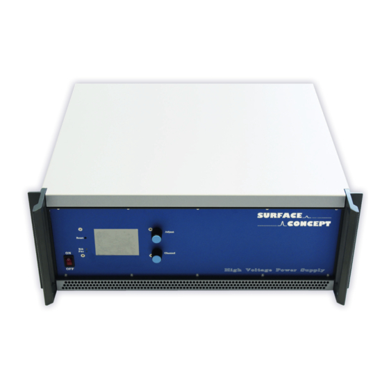
2.3 General Overview The Surface Concept 19” Basic Unit R015 is base unit of a modular supply system which can be equipped with up to 9 individual modules like high voltage power supply modules, current source modules etc. It comes with an integrated main controller, which allows a communication between the Basic Unit and the single modules via an integrated bus system. -
Page 7: Introduction
3.1 Initial Inspection Visual inspection of the system is required to ensure that no damage has occurred during shipping. If there are any signs of damage, please contact SURFACE CONCEPT immediately. Please check the delivery according to the packing list (see Table 1) for completeness. - Page 8 19“ Basic Unit Manual | Surface Concept GmbH...
-
Page 9: Device Layout & Operation
7. BNC connector for hardware interlock (output of BNC connector must be grounded to deactivate interlock) 8. Ground connector for device grounding 9. Ethernet socket 10. Power socket Figure 1: Layout of the 19” Basic Unit R015. 19“ Basic Unit Manual | Surface Concept GmbH... -
Page 10: General Device Operation
4.2 General Device Operation After switching on the device (1), the display (4) shows the “Surface Concept” animated logo, while the device is scanning for available modules and their specific settings. This can take up to several seconds. If the device is ready for operation, it switches into the standby mode and shows an empty mask for the... -
Page 11: Additional Device Options
19” Basic Unit. Not all listed functions are available for each single module layout. The “HV Master Tracking” allows the HVPS to track an external reference voltage and to produce an output voltage which is in a fixed defined relation to the master voltage. -
Page 12: Contact Surface Concept
5.2 Contact Surface Concept The sub-menu “Contact Surface Concept” in the device options displays the Surface Concept contact information. Press the “Exit” button to leave this sub-menu. Figure 7: “Contact Surface Concept” sub-menu. 19“ Basic Unit Manual | Surface Concept GmbH... -
Page 13: Error States
Please terminate the interlock to ground using either the BNC termination plug (part of the delivery) or check the proper functionality of the use device which is providing the interlock. Figure 8: Error code – Interlock. 19“ Basic Unit Manual | Surface Concept GmbH... - Page 14 19“ Basic Unit Manual | Surface Concept GmbH...
-
Page 15: Technical Data
19“ Basic Unit R015 R033 Housing Dimensions (h/w/d): 177mm x 462mm x 496mm No. of Slots for Modules: Electrical Input (LINE): 85V – 260V AC, 50/60Hz Power (max.): 500W Fuse: 1 x T 3.15A 19“ Basic Unit Manual | Surface Concept GmbH... - Page 16 19“ Basic Unit Manual | Surface Concept GmbH...
-
Page 17: List Of Figure
.......................... 10 Figure 5: “Device Options” sub-menu..............................11 Figure 6: “Special Functions Check” sub-menu..........................11 Figure 7: “Contact Surface Concept” sub-menu..........................12 Figure 8: Error code – Interlock................................13 19“ Basic Unit Manual | Surface Concept GmbH... - Page 18 Electromagnetic compatibility (EMC): Generic standards - Emission standard for industrial environments EN 61010-1: 2010 Safety Requirements for Electrical Equipment for Measurement, Control and Laboratory Use For and on behalf of Surface Concept GmbH Legal Signature………………………………………… Mainz,……01.04.2013………. (Date) (Dr. Andreas Oelsner) This declaration does not represent a commitment to features or capabilities of the instrument.


Need help?
Do you have a question about the HVPS and is the answer not in the manual?
Questions and answers