Table of Contents
Advertisement
Quick Links
Advertisement
Table of Contents

Related Manuals for Surface Concept MCPD40


Summary of Contents for Surface Concept MCPD40
- Page 1 1-Channel MCP Detector MCPD40 1-Channel MCP Detector MCPD40 (Release 006) Manual...
- Page 2 Am Sägewerk 23a 55124 Mainz Germany phone: +49 6131 62716 0 1-Channel MCP Detector fax: +49 6131 62716 29 MCPD40 Release 006 email: info@surface-concept.de Manual Version 2.1 web: www.surface-concept.de Printed on 2019-08-16 1-Channel MCP Detector MCPD40 Manual | Surface Concept GmbH...
-
Page 3: Table Of Contents
6.4 Operation .......................... 14 6.5 MCP Lifetime and Operation Voltage ..............14 6.6 MCP Degase Procedure ....................17 6.7 Replacement ........................17 7 Technical Data ......................... 18 8 List of Figure ..........................19 1-Channel MCP Detector MCPD40 Manual | Surface Concept GmbH... -
Page 4: Introduction
It is divided into 8 chapters. The chapter “Introduction” contains a brief description of the Detector. The chapter “Installation” refers to installation and cabling. Chapter “Operation of the MCPD40” describes the operation of the detector. The final chapters contain amongst others technical details about the microchannel plates and the MCP detector. -
Page 5: General Overview Of The System
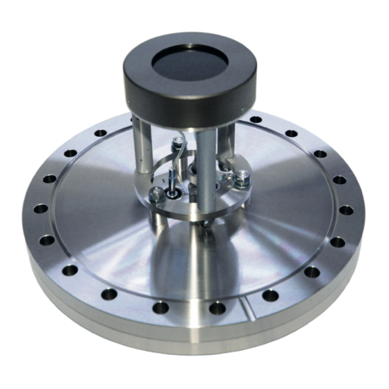
1-Channel MCP Detector MCPD40 Manual 2.3 General Overview of the System The Surface Concept MCPD40 R006 is a 1-Channel MCP Detector. It consist of a chevron microchannel plate stack and a detector anode. MCP pulses are capacitively coupled into the anode. The anode is a 50Ohm matched system and signal readout is realized close to ground via a coaxial cable and connector layout. -
Page 6: Installation
3 Installation 3.1 Initial Inspection Visual inspection of the MCPD40 is required to ensure that no damage has occurred during shipping. Should there be any signs of damage, please contact your provider immediately. 3.2 Installation 3.2.1 Mounting the MCPD Detector The detector is packed under vacuum. -
Page 7: Cabling And High Voltage
Be sure that all voltages are settled to zero before connecting the high voltage cables to the detector, otherwise serious damage to the detector can occur due to high voltage sparks. 1-Channel MCP Detector MCPD40 Manual | Surface Concept GmbH... -
Page 8: Operation Of The Mcpd40
Start the “Start-Up” procedure again with an increased ramp time. Turn off the high voltage completely, stop the procedure and call your provider for further assistance, if is it not possible to reach the operation voltage without sparking. 1-Channel MCP Detector MCPD40 Manual | Surface Concept GmbH... -
Page 9: Dark Count Rate Measurement
After finishing the dark count rate measurement with a satisfying result, you may now start carefully with an electron or light source observing the detector output. Turn off the high voltage before performing any changes of the cabling. 1-Channel MCP Detector MCPD40 Manual | Surface Concept GmbH... -
Page 10: Standard Operation Procedure
The use of heating tapes and jackets is not recommended, due to danger of local overheating. • Do not remove the blankets until the entire system has thoroughly cooled off. • Do not operate the detector before the temperature has returned to ambient conditions. 1-Channel MCP Detector MCPD40 Manual | Surface Concept GmbH... -
Page 11: Mcp Detector Layout
5.1 MCPD40 - Vacuum Wiring The MCP detector MCPD40 consist of a detection area, defined by the MCP holders and the detector anode. The front side of the detector anode is on high voltage potential, while the signal readout is realized close to ground potential (in respect to the high voltage of the MCPs). -
Page 12: Filterbox
5.2 Filterbox The MCPD40 might come with an additional filterbox for the signal output to minimize noise effects on the signal line, which comes from external sources. Connect the filterbox with the short cable to the BNC feedthrough of the MCPD40 and connect your signal readout to the BNC connector of the filterbox. -
Page 13: Microchannel Plate
Voltages must not be applied to the device while at atmospheric pressure. The pressure should be 1E-6mbar or lower at the microchannel plate before applying voltage. Otherwise, damaging ion feedback or electrical breakdown will occur. 1-Channel MCP Detector MCPD40 Manual | Surface Concept GmbH... -
Page 14: Operation
The typical gain degradation of a MCP is shown in Figure 6 as a function of extracted output charge in terms of coulombs per square centimeter. Figure 6: Typical gain degradation of MCPs as function of the extracted output charge. 1-Channel MCP Detector MCPD40 Manual | Surface Concept GmbH... - Page 15 1-Channel MCP Detector MCPD40 Manual | Surface Concept GmbH...
- Page 16 MCP curve with the specified operation voltage. The MCP curve for specifying the starting operation voltage for a detector can always be found in the specification sheet. Figure 8: Example of MCP curve (for illustration only). 1-Channel MCP Detector MCPD40 Manual | Surface Concept GmbH...
-
Page 17: Mcp Degase Procedure
MCPs must be mounted in a chevron configuration. All parts of the detector, especially the MCPs should be handled with great care. The MCP surfaces are very sensitive and should never be touched or scratched. 1-Channel MCP Detector MCPD40 Manual | Surface Concept GmbH... -
Page 18: Technical Data
2 SHV connectors (MCP front, detector anode + MCP back) Connections for signal: 1 BNC connector (50Ohm matched coaxial signal) Max. bake-out temperature: 150°C Vacuum pressure range for operation: <1E-6 mbar 1-Channel MCP Detector MCPD40 Manual | Surface Concept GmbH... -
Page 19: List Of Figure
1-Channel MCP Detector MCPD40 Manual 8 List of Figure Figure 1: Connection scheme of the MCPD40 R006..............................7 Figure 2: Schematic sketch on voltage ramping during “Start-Up” procedure....................9 Figure 3: Layout of the HV connections and photos of the single detector elements................. 11 Figure 4: Internal connection of the high voltage potentials (schematic) for the R006..
Need help?
Do you have a question about the MCPD40 and is the answer not in the manual?
Questions and answers