Table of Contents
Advertisement
Quick Links
•
Monitoring of zone
• Controls specific to
temperature and RH
Controlled
Environment
•
Real-time monitoring
Agriculture
and control of airflow
• Monitoring of
•
Optional VOC
temperature, RH,
dew point, and VPD
sensor control of
ventilation air
• Photocell input
allows for feedback
•
Low exhaust fan
of light cycle
control
• Optional CO
•
Economizer
2
monitoring and
capability
automated control
•
Cloud-based logging,
• Capability to link
alarms, and control
units for coordinated
control in a single
when used with
space
AireGuard
TM
• Cloud-based logging,
alarms, and control
when used with
AireGuard™
CM3560 Series
Controller
Installation and Operation Manual
Installation and Operation Manual for SP Units
for GA, GS and GV Units
6
6
Advertisement
Table of Contents

Related Manuals for Desert Aire CM3560 Series


Summary of Contents for Desert Aire CM3560 Series
- Page 1 CM3560 Series Controller Installation and Operation Manual Installation and Operation Manual for SP Units for GA, GS and GV Units • Monitoring of zone • Controls specific to temperature and RH Controlled Environment • Real-time monitoring Agriculture and control of airflow •...
- Page 3 TERMS Desert Aire warrants all components (except as noted) for a period of two (2) years from the date of shipment. This warranty shall be limited to the supply of new or rebuilt parts for the part which has failed because of defects in workmanship or material, and does not include the cost for labor, transportation or other costs not herein provided for.
- Page 4 E-MAIL: service@desert-aire.com Additional copies of this manual can be purchased for a nominal fee from Desert Aire. Desert Aire also posts the most current revision of our I/O Manuals on our website. For a digital copy of the I/O Manual for your unit revision, please submit request to the contact information listed above.
- Page 5 Product Warning for the State of California Desert Aire - CM3560 Manual...
- Page 6 Desert Aire - CM3560 Manual...
-
Page 7: Table Of Contents
2.3.3.2.5. Tuning – Outdoor Air Pre-Heating (Figure 72 & 73) ..2.3.3.2.6. Tuning – Maximum Outdoor Air (Figure 74) ....2.3.3.3 I/O Status (Figure 75) ..............2.3.3.3.1 Digital Inputs (Binary) (Figure 76 through 80) ....Desert Aire - CM3560 Manual... - Page 8 Discharge & Liquid Pressure Transducers .............. Suction, Liquid, Pool & Supply Air Temperature Sensors ........Zone and Outdoor Air Temperature and Relative Humidity Sensors ....... Differential Air Pressure Sensors ................Appendix ......................... Internal Web Page ....................Desert Aire - CM3560 Manual...
-
Page 9: Installation
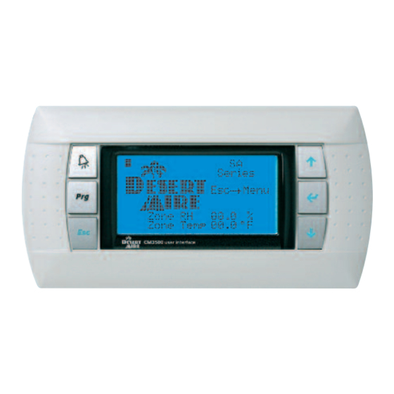
1 Installation Introduction Your Desert Aire controller is designed for precise monitoring and control of air temperature and relative humidity (RH) within a conditioned environment. This CM3560 control system is easy to install and operate. The controller features an internal display terminal (IDT). This display allows viewing and adjustment of the unit’s sensors and setpoints. -
Page 10: Unit Sensor Installation
Auxiliary Air Heating Control Wiring Note: You must use the Desert Aire CM3560 control system to control or interlock with the room heating system. This prevents wide fluctuations in room air temperature. It also prevents the heater from trying to heat the room while the dehumidifier is running in the cooling mode. -
Page 11: Auxiliary Heating - Proportional Signal
1.3.2 Auxiliary Heating - Proportional Signal Desert Aire will provide a proportional 0-10 VDC direct-acting signal to modulate a heating coil control valve or other auxiliary modulating heater. Most proportional valves have either three (3) or four (4) terminals for field- installed wiring. -
Page 12: Cm3560 Controller Details
Controller Details Menu Overview and General Instructions (Figure 1) Your Desert Aire controller is pre-programmed and configured at the factory for use in the application you have specified. The internal display terminal (IDT, see Figure 1) allows the operator to monitor and adjust the setpoints of your Desert Aire system. - Page 13 UP or DOWN arrow keys. If the operator has not pressed a key for an hour, the display will return to the Home Screen. Figure 1 Desert Aire - CM3560 Manual...
-
Page 14: Zone Setpoints (Figure 2)
ENTER key to modify. Pool 2 setpoint will be shown in a similar manner when a second pool condenser is supplied with the dehumidifier. To return to the MAIN MENU, press the Esc key. Figure 3 Desert Aire - CM3560 Manual... -
Page 15: Main Menu (Figure 4)
“BMS has Disabled Unit” if the BMS has turned the unit off. The date and time will be shown on the bottom line. To return to the STATUS MENU, press the Esc key. Figure 5 Desert Aire - CM3560 Manual... - Page 16 EXV of Circuit A along with the superheat, suction temperature, suction pressure suction P2T, steps and percent open of the EVX. This screen is for troubleshooting only. To return to the STATUS MENU, press the Esc key. Desert Aire - CM3560 Manual...
-
Page 17: Occupacy Schedule (Figure 10)
‘Yes’, and press ENTER. The schedule will need to be setup before this will be enabled. Pressing the Prg key from this menu allows the date and time to be modified. To return to the MAIN MENU, press the Esc key. Figure 10 Desert Aire - CM3560 Manual... -
Page 18: Time/Date (Figure 11)
Copy To: the appropriate day, and then selecting Ok? to ‘Yes’. Modify these days as appropriate. To return to the OCCUPANCY SCHEDULE MENU, press the Esc key. Figure 12 Desert Aire - CM3560 Manual... -
Page 19: Vacation Periods (Figure 13)
2.3.2.4 Special Days (Figure 14) Also available are 6 special days where the full day can be set for either ‘Occupied’ or ‘Un-Occupied’. To return to the OCCUPANCY SCHEDULE MENU, press the Esc key. Figure 14 Desert Aire - CM3560 Manual... -
Page 20: Temporary Occupancy (Figure 15)
Selecting the SERVICE MENU will display the Login Screen (Figure 16). Enter the service password, 1234, and press ENTER. Figure 16 The SERVICE MENU gives access to Commissioning, Tuning, I/O Status, Sensor Offsets and Memory Options. (Figure 17) Desert Aire - CM3560 Manual... -
Page 21: Commissioning (Figure 18)
A and B. This screen also allows the settings for the tower and pool flow switches to be modified. Press the DOWN key for the next Configuration screen. To return to the Service Menu, press the Esc key. Desert Aire - CM3560 Manual... - Page 22 The Pump screens allow modification to the Pump Minimum On and Minimum Off time as well as the allowable delay for making the flow switch. The water flow status is also shown here. Figure 20 Figure 21 Desert Aire - CM3560 Manual...
- Page 23 If the Low Exhaust option has been provided, the screen in Figure 24 will be shown. This screen allows the settings for the Low Exhaust VFD speeds in the selected air modes. To return to the Service Menu, press the Esc key. Desert Aire - CM3560 Manual...
- Page 24 PID loop that is in control. Press the Esc key to return to Figure 25. Pressing the DOWN key will display the screen shown in Figure 28. Figure 25 Figure 26 Desert Aire - CM3560 Manual...
- Page 25 ENTER key and use the arrow keys until the desired setting is shown. Pressing the ENTER key will now change the term. The current oudoor air relative humidity and damper position are shown as well. Desert Aire - CM3560 Manual...
-
Page 26: Supply Blower Setup (Figure 31)
The speed of the blower can be placed in manual control from this screen and a manual speed set for troubleshooting. The altitude that the CFM calculation uses is settable on this screen as well. Desert Aire - CM3560 Manual... - Page 27 Pressing the DOWN key will display either the screen shown on Figure 33 or 34 depending on the presence of back draft dampers. These screens are shown for troubleshooting the supply blower CFM. To return to the Commissioning Menu, press the Esc key. Desert Aire - CM3560 Manual...
-
Page 28: Exhaust Blower Setup (Figure 35)
Commissioning Menu, press the Esc key. Figure 35 Pressing the DOWN key will display the screen shown in Figure 36. The maximum exhaust flow rates are set from this screen for each air mode of operation. Desert Aire - CM3560 Manual... - Page 29 ENTER key and use the arrow keys until the desired setting is shown. Pressing the ENTER key will now change the term. The Setpoint, current pressure and the loop output are also shown. Desert Aire - CM3560 Manual...
- Page 30 Set this value in the un-occupied mode to insure no air is leaving the unit. To return to the Commissioning Menu, press the Esc key. Figure 39 Figure 40 Desert Aire - CM3560 Manual...
-
Page 31: Airflow Setup (Figure 41)
To modify these terms, press the ENTER key and use the arrow keys until the desired setting is shown. Pressing the ENTER key will now change the term. The Setpoint, current O/A CFM and the loop output are also shown. Desert Aire - CM3560 Manual... - Page 32 ENTER key and use the arrow keys until the desired setting is shown. Pressing the ENTER key will now change the term. The Setpoint, current pressure drop and the loop output are also shown. Figure 45 Desert Aire - CM3560 Manual...
- Page 33 Figure 48. The CFM Setpoints for using the Perforated Plate formulas are set here. To modify these settings, press the ENTER key and use the arrow keys until the desired setting is shown. Pressing the ENTER key will now change the setting. Desert Aire - CM3560 Manual...
- Page 34 Figure 48. To modify these settings, press the ENTER key and use the arrow keys until the desired setting is shown.Pressing the ENTER key will now change the setting. Figure 49 Figure 50 Desert Aire - CM3560 Manual...
- Page 35 Manual mode, change the ‘A’ to ‘M’. Modify the percentage setting to move the actuator. Note that these settings are lost on a power cycle, so the unit will return to normal control mode. Figure 53 Desert Aire - CM3560 Manual...
-
Page 36: Bms Setup (Figures 55 Through 62)
Figure 55 Pressing the DOWN key will display Figure 56. This screen will allow the BACnet data to be set. Making any changes will require a power cycle to have those changes take effect. Desert Aire - CM3560 Manual... - Page 37 Once set, pressing the DOWN key will display Figure 58. Figure 58 Pressing the DOWN key again will display the port setup for BACnet IP. This allows the Device ID and Port to be set. Desert Aire - CM3560 Manual...
- Page 38 Ethernet subnet to be sent to any other unit on that subnet. The first three octets of the IP address must be the same as well. In order to prevent network faults from shutting down the dehumidifier, DHCP must be turned “Off” and a Desert Aire - CM3560 Manual...
-
Page 39: Tuning - Dead Bands (Figure 63)
Figure 63. The default settings for the dead bands can be modified on this screen. The Heating Deadband value is subtracted from the Zone Temperature Setpoint from section 2.2. This value is the Desert Aire - CM3560 Manual... -
Page 40: Tuning - Differentials (Figure 64)
Differential is 0.0° F to 9.9° F. The range of the Humidity Differential is 0.0% to 9.9%. Press the DOWN key for the next Tuning screen. To return to the Service Menu, press the Esc key. Desert Aire - CM3560 Manual... -
Page 41: Tuning - Energy Recovery (Figure 65)
Stage Deadband for enabling external auxiliary pool heat. The inlet and outlet temperatures are shown here as well. To return to the Service Menu, press the Esc key. Desert Aire - CM3560 Manual... -
Page 42: Tuning - Air Heating (Figures 68 Through 71)
These settings control the modulating signal. Figure 69 allows inverting the heat signal for water valve operation and varying the heat output from 0-10VDC to 2-10VDC, if desired. Also shown are the settings for the percentage to disable the Desert Aire - CM3560 Manual... - Page 43 Figure 71. This shows the zone reset PID and limits settings and the calculated heating setpoint. To return to the Service Menu, press the Esc key. Figure 69 Figure 70 Figure 71 Desert Aire - CM3560 Manual...
-
Page 44: Tuning - Outdoor Air Pre-Heating (Figure 72 & 73)
VOC readings above the Setpoint will enable the Max OA Mode and readings below the setpoint minus the Differential will disable this mode. The current reading of the VOC sensor is shown also. To return to the Service Menu, press the Esc key. Desert Aire - CM3560 Manual... -
Page 45: I/O Status (Figure 75)
“Flt” if an overload exists. • The fourth line will show the status of ID4 the circuit A compressor motor starter overload contacts - “Ok” if no overload is present, and “Flt” if an overload exists. Desert Aire - CM3560 Manual... - Page 46 The third page shows the state of the next four contacts wired into the controller. • The first line will show the status of ID11 the low exhaust blower motor starter overload contact. “OK” if the contact is closed, and “Flt” if an overload exists. Desert Aire - CM3560 Manual...
- Page 47 “OK” if the filter pressure is low, and “Flt” if the filter pressure is high. • The sixth line will show the status of DI2 on port J29, the optional condensate switch, “OK” if the level is low, and “Flt” if level is high. Desert Aire - CM3560 Manual...
- Page 48 “OK” if the contact is closed, and “Flt” if the contact is open. • The sixth line will show the status of U10 VFD146 VFD fault contact. “OK” if the contact is closed, and “Flt” if the contact is open. Figure 80 Desert Aire - CM3560 Manual...
-
Page 49: Analog Inputs (Figures 81 Through 90)
A. Figure 82 The third page shows the readings of the liquid pressure and temperature sensors, the calculated P2T value of the liquid pressure sensor and the Subcooling values of circuit A. Figure 83 Desert Aire - CM3560 Manual... - Page 50 P2T value of the liquid pressure sensor and the Subcooling values of circuit B. Figure 85 The sixth page shows the readings of the air pressure differential sensors as shown. Figure 86 Desert Aire - CM3560 Manual...
- Page 51 The ninth page shows the readings of optional air pressure differential sensors that are provided if the back draft damper option has been provided. Figure 89 To return to the I/O STATUS screen, press the Esc key. Desert Aire - CM3560 Manual...
-
Page 52: Digital Outputs (Binary) (Figures 87 Through 93)
• The fourth line will show the status of C12, the Supply Blower VFD Enable contact, “On” and “Off”. • The fifth line will show the status of C13, the Exhaust Blower VFD Enable contact, “On” and “Off”. Desert Aire - CM3560 Manual... - Page 53 • The third line will show the status of C3 address 4, the Outdoor Air Pre-Heat Enable contact, “On” and “Off”. • The third line will show the status of C6 address 4, the Pool 2 Pump contact, “On” and “Off”. Desert Aire - CM3560 Manual...
-
Page 54: Analog Outputs (Figures 94 Through 97)
• Outdoor Air Damper Command Figure 94 The second page shows the state of the next four outputs. • Supply Blower Speed Command • Exhaust Blower Speed Command • Outdoor Air Bypass Damper Command • Air Heat Modulating Command Desert Aire - CM3560 Manual... -
Page 55: Sensor Offsets (Figures 97 - 103)
To modify the offsets, press the ENTER key until the desired offset is selected and use the arrow keys until the desired setting is shown. Press the ENTER key to accept the offset value. Desert Aire - CM3560 Manual... - Page 56 Figure 97 Figure 97 Figure 98 Figure 99 Figure 100 Desert Aire - CM3560 Manual...
-
Page 57: Memory Options (Figures 104 - 106)
Log. csv and the Data Log.csv. Both of this can be opened in Excel. The Alarm Log takes a snapshot of the conditions whenever an Alarm is triggered. The Data Log records values every minute of operation for the past month. Desert Aire - CM3560 Manual... -
Page 58: Unit Revision (Figure 107)
The Unit Revision Screen shows the version of the application program that is running along with the release date of the software. This information should be passed to Desert Aire in the event a service call is necessary. Desert Aire - CM3560 Manual... -
Page 59: Alarm Menu
Figure 109 To reset the alarm, use the DOWN key until the reset instructions are shown. See Figure 110. Pressing the ALARM key for three seconds will reset all active alarms. Desert Aire - CM3560 Manual... -
Page 60: System Alarms
The bottom two lines will show the pertinent data that was recorded when the alarm occurred. Use the UP and DOWN keys to view other records. To return to the home screen, press the Esc button. Desert Aire - CM3560 Manual... -
Page 61: Hardware Details
Figure 111 4 Hardware Details Programmable Controller The programmable controller is preprogrammed by Desert Aire for the control of your unit. The Desert Aire replacement part number for this controller is available by calling our service department. Suction Pressure Transducers The Suction Pressure Transducer is a 0.5 - 4.5 VDC to 0 - 250 psig ratio metric device. -
Page 62: Discharge & Liquid Pressure Transducers
-623.3° F if the sensor is open, and display a reading of 687.3° F if the sensor is shorted. The Desert Aire replacement part number for the Supply Air Temperature Sensor is available by calling our service department. -
Page 63: Appendix
Appendix 5.1 Internal Web Page The programmable controller is preprogrammed by Desert Aire to include a web page allowing a virtual remote display to be used from any node on the facilities computer network. Simply attach an Ethernet cable from your facilities computer network to the RJ45 port of the controller. - Page 64 PTIMIZING OLUTIONS HROUGH UPERIOR EHUMIDIFICATION ECHNOLOGY N120 W18485 Friestadt Road, Germantown, WI 53022 sales@desert-aire.com Ph: (262) 946-7400 Fax: (262) 946-7401 Website: www.desert-aire.com 461 2020/12...
Need help?
Do you have a question about the CM3560 Series and is the answer not in the manual?
Questions and answers