Desert Aire CM3510 Installation And Operation Manual
For sa units, remote display terminal
Hide thumbs
Also See for CM3510:
- Installation and operation manual (60 pages) ,
- Installation and operation manual (64 pages)
Table of Contents
Advertisement
Quick Links
• Backlit LCD User
Interface
• Programmed by
Desert Aire for
dehumidification and
temperature control
• Multiple communication
interface options:
- LonWorks
®
- BACnet™ Ethernet
- BACnet™ MS/TP
- Modbus
®
• Alarm history retention
• Internal time clock for
stand alone operation
Installation and Operation Manual for SA Units
Advertisement
Table of Contents

Related Manuals for Desert Aire CM3510


Summary of Contents for Desert Aire CM3510
- Page 1 Installation and Operation Manual for SA Units • Backlit LCD User Interface • Programmed by Desert Aire for dehumidification and temperature control • Multiple communication interface options: - LonWorks ® - BACnet™ Ethernet - BACnet™ MS/TP - Modbus ® • Alarm history retention •...
- Page 3 TERMS Desert Aire warrants all components (except as noted) for a period of two (2) years from the date of shipment. This warranty shall be limited to the supply of new or rebuilt parts for the part which has failed because of defects in workmanship or material, and does not include the cost for labor, transportation or other costs not herein provided for.
- Page 4 E-MAIL: service@desert-aire.com Additional copies of this manual can be purchased for a nominal fee from Desert Aire. Desert Aire also posts the most current revision of our I/O Manuals on our website. For a digital copy of the I/O Manual for your unit revision, please submit request to the contact information listed above.
- Page 5 Product Warning for the State of California: Desert Aire - CM3510 Manual...
- Page 6 Desert Aire - CM3510 Manual...
-
Page 7: Table Of Contents
TABLE OF CONTENTS Overview ..........................Field Installation of CM3510 Control Sensors ............. 1.1.1 Duct-Mounted Sensor ................1.1.2 Wall Mount Humidity and Temperature Sensor ........1.1.3 Water Temperature Sensor (Pool Water Heating Option Only) ....Auxiliary Air Heating Control Wiring ............... 1.2.1 Auxiliary Heating - Dry Contact Closure ............ - Page 8 Suction Pressure Transducer ................. Discharge Pressure Transducer ................Differential Air Pressure Transducer ............... Temperature Sensor ....................Zone Air Temperature and Relative Humidity Sensor ..........Appendix ..........................Remote Communication ..................4.1.1 BACnet Ethernet ..................4.1.2 BACnet MS/TP ................... Desert Aire - CM3510 Manual...
-
Page 9: Overview
Overview The CM3510 operating controller installed in Desert Aire’s SA dehumidifer is designed for precise control and monitoring of air temperature and relative humidity (RH) within the conditioned space. Additionally the control will capture and retain alarm history to aid in equipment troubleshooting. -
Page 10: Auxiliary Air Heating Control Wiring
1.2. Auxiliary Air Heating Control Wiring Note: You must use the Desert Aire CM3510 control system to control or interlock with the room heating system. This prevents wide fluctuations in room air temperature. It also prevents the heater from trying to heat the room while the dehumidifier is running in the cooling mode. - Page 11 Optional communication modules for interface to building automation system. Lonworks®, BACnet™ Ethernet, BACnet™ MS/TP, and Modbus® communication modules are available. • For BMS Points Lists please send inquiry to service@desert-aire.com and include your model number, serial number and BMS protocol. Desert Aire - CM3510 Manual...
- Page 12 Desert Aire - CM3510 Manual...
-
Page 13: Sa Controller Details
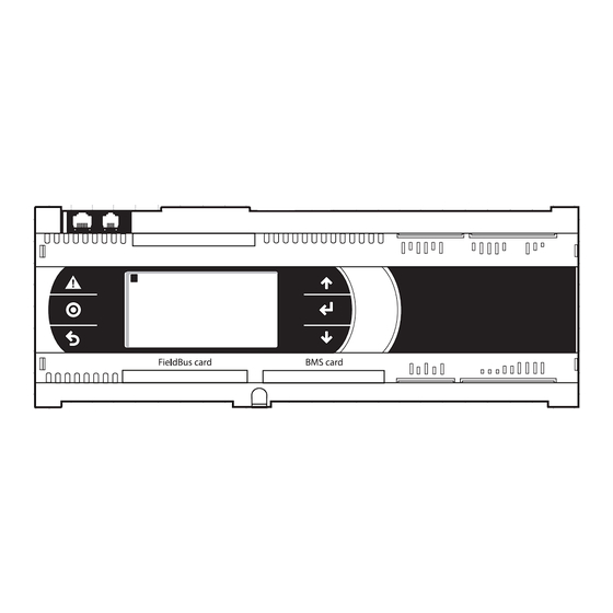
The Remote Display Terminal (RDT - Figure 1) allows the operator to monitor and adjust the set points of your Desert Aire SA dehumidifier. The RDT has an LCD screen and 6 keys. The keys on the left hand side of the LCD screen are the ALARM key shown as an alarm bell, PROGRAM key abbreviated “Prg”... -
Page 14: Main Menu
Figure 2 To return to the Home Screen, press the Esc key. 2.2.1 Status Menu Selecting the STATUS MENU from the MAIN MENU allows access to the UNIT STATUS, I/O Status, Pressure Cutouts & EXV Status. Desert Aire - CM3510 Manual... -
Page 15: Unit Status
“VOC High” will appear on the right side of the fifth line. The sixth line will display if the BMS option has been turned on in the Factory Configuration of the unit. Pressing the DOWN key from this menu displays the status of Circuit A. Desert Aire - CM3510 Manual... - Page 16 Pressing the UP key displays the Unit Status screen. Pressing the DOWN key displays the Circuit B Status screen. Figure 5 To return to the STATUS MENU, press the Esc key. Desert Aire - CM3510 Manual...
-
Page 17: I/O Status
Your unit will almost certainly vary. Refer to the unit specific schematic diagrams for the actual devices that have been provided. Desert Aire - CM3510 Manual... -
Page 18: Digital Inputs (Binary)
Digital Inputs screens. Figure 8 Water Coil T’Stat – This is only used for freeze protection of a water or steam coil. “On” if the temperature is acceptable, and “Off” if the temperature is low. Desert Aire - CM3510 Manual... - Page 19 “Off” if the contact is open. Exhst Blower OL – The exhaust blower overload contact will show “On” if the contact is closed which is normal, and “Off” if the contact is open to indicate a fault. Desert Aire - CM3510 Manual...
- Page 20 The fourth page of the digital input screen is shown in Figure 11 and is accessible by pressing the DOWN key. This is an optional screen and will only be shown when the unit is configurable for pool or tower water condenser. Desert Aire - CM3510 Manual...
- Page 21 The fifth page of the digital input screen series is shown in Figure 12 and is accessible by pressing the DOWN key. This is an optional screen and will only be shown when the unit is configurable for a second pool or second tower water condenser. Figure 12 Desert Aire - CM3510 Manual...
-
Page 22: Analog Inputs
The first Analog Inputs screen, Figure 14, shows the status of the Discharge Pressure in circuits A and B, the Zone Air Relative Humidity and Temperature and the Supply Air Temperature. Desert Aire - CM3510 Manual... - Page 23 The third Analog Inputs screen, Figure 16, shows the status of the A circuit suction pressure and temperature as well as the calculated P2T temperature from the suction pressure. The superheat of the circuit and the discharge pressure are also shown. Desert Aire - CM3510 Manual...
- Page 24 P2T temperature from the suction pressure. The superheat of the circuit and the discharge pressure are also shown. Figure 17 The fifth Analog Inputs screen, Figure 18, shows the status of the air pressure transducers used in the system. Desert Aire - CM3510 Manual...
-
Page 25: Digital Outputs (Binary)
J7 & J8 of the optional Expansion Boards. These screens are provided for troubleshooting the control system. The first Digital Ouputs screen, Figure 20, shows the status of the Compressor and 1-SOL outputs for circuits A and B. Desert Aire - CM3510 Manual... - Page 26 The third Digital Outputs screen, Figure 22, shows the status of the optional expansion board 1 used for the Pool 1 auxiliary heat and pump output, the tower 1 pump output and to enable air heating. Desert Aire - CM3510 Manual...
- Page 27 2 used for the Pool 2 auxiliary heat and pump output and the tower 2 pump output. Figure 23 The fifth Digital Outputs screen, Figure 24, shows the status of the optional expansion board 3 used for the Low Exhaust Blower. Desert Aire - CM3510 Manual...
-
Page 28: Analog Outputs
Expansion Boards. These screens are provided for troubleshooting the control system. The first Analog Outputs screen, Figure 26, shows the position of the Bypass Damper, Cool Air Damper, Warm Air Damper and Outdoor Air Damper. Desert Aire - CM3510 Manual... - Page 29 To return to the I/O STATUS screen, press the Esc key. Figure 27 To return to the STATUS MENU, press the Esc key. Desert Aire - CM3510 Manual...
-
Page 30: Pressure Cutouts
A. The super heat, suction temperature, suction pressure and calculated saturation temperature are shown as well as the position of the valve in steps and opening percentage. Figure 30 shows the same data for circuit B. Figure 29 Desert Aire - CM3510 Manual... -
Page 31: Setpoint Menu
Figure 31 If pool heating is included in the unit, Figure 32 will be displayed. Select the appropriate item with the UP and DOWN keys and press the ENTER key to select. Desert Aire - CM3510 Manual... -
Page 32: Occupancy Schedule
To return to the SETPOINT MENU, press the Esc key. 2.2.3 Occupancy Schedule Select the OCCUPANCY SCHEDULE, from the MAIN MENU to show the OCCUPANCY SCHEDULE MENU. From this menu you can access and adjust the Schedule Options, Temporary Holidays, Annual Holidays, Temporary Occupancy or Desert Aire - CM3510 Manual... -
Page 33: Schedule Options
Current Schedule Screen. If the number of active schedules is left at zero, no occupancy scheduling will be active. See Figure 35. To return to the OCCUPANCY SCHEDULE MENU, press the Esc key. Figure 35 Desert Aire - CM3510 Manual... -
Page 34: Temporary Holidays
Memorial Day or Thanksgiving. See Figure 37. Up to 10 different temporary holidays can be set from this screen. Select the number to assign to the Annual Holiday and then select the Start Date and the End Date for that holiday. Desert Aire - CM3510 Manual... -
Page 35: Annual Holidays
10 different annual holidays can be set from this screen. Select the number to assign to the Annual Holiday and then select the Start Date and the End Date for that holiday. Figure 38 To return to the OCCUPANCY SCHEDULE MENU, press the Esc key. Desert Aire - CM3510 Manual... -
Page 36: Temporary Occupancy
Figure 40 will be shown. Selecting any of these options will allow an override to be active for that mode. The override of the event or purge modes work in the same manner as detailed in section 2.2.3.4 for the temporary occupancy. Desert Aire - CM3510 Manual... -
Page 37: Set Time
Pressing the ENTER key will step to the next item. If any item was modified, the message “Enter to Set” will be shown. Press the ENTER key to accept the time and date values. Figure 41 To return to the OCCUPANCY SCHEDULE MENU, press the Esc key. Desert Aire - CM3510 Manual... -
Page 38: Service Menu
Recovery, Pool 1 Settings or Pool 2 Settings. The Energy Recovery Settings will only be shown if an SA unit with an Exhaust mode is provided and the Pool settings screen will only be shown if pool heating is provided. Desert Aire - CM3510 Manual... -
Page 39: Deadbands
Figure 45 shows the operation of an SA unit without an exhaust fan or an SA unit with an exhaust fan & in unoccupied mode. Figure 46 shows the operation of an SA unit in occupied mode. Desert Aire - CM3510 Manual... - Page 40 Figure 44 14.5 CU. FT. 12.5 CU. FT. 13.0 CU. FT. DRY BULB °F 13.5 CU. FT. 14.0 CU. FT. Figure 45 Desert Aire - CM3510 Manual...
-
Page 41: Air Differentials
Humidity Differential is 0.0% to 9.9%. To modify the differentials, press the ENTER key and use the arrow keys until the desired setting is shown. Press the ENTER key to accept set point value. Desert Aire - CM3510 Manual... -
Page 42: Energy Recovery
ENTER key and use the arrow keys until the desired setting is shown. Press the ENTER key to accept the set point value. Figure 48 To return to the TMP/RH/POOL SETTINGS Screen, press the Esc key. Desert Aire - CM3510 Manual... -
Page 43: Pool 1 Or 2 Settings
ENTER key and use the arrow keys until the desired setting is shown. Press the ENTER key to accept set point value. See Graphic in Figure 50 for an illustration of the operation of the pool temperature control. Figure 49 Figure 50 Desert Aire - CM3510 Manual... -
Page 44: Aux Heat Settings
The current Zone Air Temperature and Supply Air Temperature are shown on line 8. The Zone Set point, loop percentage and the time period are settable on this screen. Desert Aire - CM3510 Manual... - Page 45 ENTER key will now change the set point. The zone temperature, the state of the heating contact and the output of this control loop are displayed at the bottom of this screen for reference. Figure 53 To return to the SERVICE MENU, press the Esc key. Desert Aire - CM3510 Manual...
- Page 46 PURGE HEATING screen allows the Air Heat Set point while in the Purge mode to be modified. The range of this set point is 45.0° to 90.0°F. The state of the heating enable contacts as well as the unit airflow mode is also shown on this screen. Desert Aire - CM3510 Manual...
-
Page 47: Cond/Roof Settings
To modify these settings, press the ENTER key and use the arrow keys until the desired setting is shown. Press the ENTER key to accept the set point values. Figure 56 Desert Aire - CM3510 Manual... - Page 48 Roof/Wall switch is closed. If the Exhaust Fan is set to disable, then the exhaust fan output will set to 0% when the Roof/Wall switch is closed. To return to the SERVICE MENU, press the Esc key. Desert Aire - CM3510 Manual...
-
Page 49: Sensor Offsets
ENTER key until the desired offset is selected and use the arrow keys until the desired setting is shown. Press the ENTER key to accept the offset value. Pressing the DOWN key will display the Expansion Board Offsets. Figure 59 To return to the SERVICE MENU, press the Esc key. Desert Aire - CM3510 Manual... -
Page 50: Airflow Menu
These set points will work concurrently with the zone pressurization. The PID loop of the CFM or Zone Pressurization that has the lowest output will drive the exhaust blower. Figure 61 To return to the Service Menu, press the Esc key. Desert Aire - CM3510 Manual... -
Page 51: Airflow Setup
Pressing the ENTER key will now change the set point. The Unit Override can be set to “Auto”, “Unocc”, “Occ”, “Event”, “Max OA” or “Purge”. This will allow testing of the damper position in all applicable modes. Desert Aire - CM3510 Manual... - Page 52 Occupancy mode, Unit mode, Exhaust mode, and the actual positions of the warm and cool exhaust damper actuators. Figure 64 To return to the Airflow Menu, press the Esc key. Desert Aire - CM3510 Manual...
- Page 53 Figure 66 will be available and allow an override to occupy the unit and determine the OA CFM Stpt, which will be set in CFM. The current calculated OA CFM will be shown below this, with the actuator position will be shown at the bottom of this screen. Desert Aire - CM3510 Manual...
- Page 54 Factory Configuration and the Max OA is enabled, the screen shown in Figure 68 will be available and allow an override to the Max OA Mode and determine the OA CFM Stpt for Max OA Mode, which will be set Desert Aire - CM3510 Manual...
- Page 55 Purge Mode and determine the OA CFM Stpt for Purge Mode, which will be set in CFM. The current calculated OA CFM will be shown below this, with the actuator position shown at the bottom of this screen. Figure 69 To return to the Airflow Menu, press the Esc key. Desert Aire - CM3510 Manual...
-
Page 56: Airflow Pid Loops
ENTER key and use the arrow keys until the desired setting is shown. Pressing the ENTER key will now change the set point. The actual zone differential air pressure and the Speed Cmd are displayed at the bottom of this screen for reference. Desert Aire - CM3510 Manual... - Page 57 The lowest calculated loop output of these loops will be the speed used to drive the exhaust blower. Figure 72 To return to the Airflow Menu, press the Esc key. Desert Aire - CM3510 Manual...
- Page 58 ENTER key and use the arrow keys until the desired setting is shown. Pressing the ENTER key will now change the set point. The actual Exhaust differential air pressure and the damper position are displayed at the bottom of this screen for reference. Desert Aire - CM3510 Manual...
- Page 59 ENTER key and use the arrow keys until the desired setting is shown. Pressing the ENTER key will now change the set point. The actual Exhaust differential air pressure and the damper position are displayed at the bottom of this screen for reference. Figure 75 Desert Aire - CM3510 Manual...
-
Page 60: Max O/A Settings
All settings can be modified from 0.0% to 100.0%. To modify these set points, press the ENTER key and use the arrow keys until the desired setting is shown. Pressing the ENTER key will now change the set point. Desert Aire - CM3510 Manual... -
Page 61: Economizer Settings
Gain is 0.0 to 3276.7. The range of the Reset is 0 to 999. The range of the Rate is 0 to 999. To modify these set points, press the ENTER key and use the arrow keys until the desired setting is shown. Pressing the ENTER key will now change the set point. The actual outside Desert Aire - CM3510 Manual... - Page 62 Pressing the ENTER key will now change the set point. The actual outside air relative humidity and damper position are displayed at the bottom of this screen for reference. Figure 80 To return to the Service Menu, press the Esc key. Desert Aire - CM3510 Manual...
-
Page 63: Unit Revision
The Unit Revision Screen shows the version of the application program that is running along with the release date of the software (Figure 81). This information should be communicated to Desert Aire in the event a service call is necessary. -
Page 64: Low Suction Pressure Circuit A Or Circuit B
Pressure rises above the High Discharge Pressure Cutout (see Section 2.2.1.3). The circuit will stop and the High Discharge Pressure Alarm will be activated. The circuit will not restart until the operator acknowledges the High Discharge Pressure Alarm AND manually resets it. Desert Aire - CM3510 Manual... -
Page 65: Supply Air Temperature Sensor Failure
This is an Automatic Reset Alarm. The System Shutdown Alarm is activated when digital input ID13 is opened. The unit will stop and the System Shutdown Alarm will be activated. The unit will restart when the digital input ID13 is closed. Desert Aire - CM3510 Manual... -
Page 66: Low Supply Air Temperature
Humidity, Supply Air Temperature, Circuit A & B Suction and Discharge Pressure and the status of the unit when the alarm occurred. To access the history of alarms, press the DOWN key. The last 100 alarm conditions are saved in this history with the 101st being overwritten. Desert Aire - CM3510 Manual... - Page 67 Figure 85 Desert Aire - CM3510 Manual...
- Page 68 Desert Aire - CM3510 Manual...
-
Page 69: Hardware Details
3.1 Programmable Controller The controller is factory programmed by Desert Aire for your unit. Replacement controllers are only available through Desert Aire or authorized Desert Aire sales representatives. If replacement is necessary please have the model number and serial number of the unit available when you contact us. -
Page 70: Differential Air Pressure Transducer
-623.3°F if the sensor is open, and display a reading of 687.3°F if the sensor is shorted. The Desert Aire replacement part number for the Supply Air Temperature Sensor is available by calling our service department. -
Page 71: Appendix
Hold the alarm button and the enter button for 5 seconds. The following screen will appear. Figure 86 • Select OTHER INFORMATION and the following screen will appear. Figure 87 • Select PCOWEB/NET CONFIG and the following screen will appear. Desert Aire - CM3510 Manual... - Page 72 After the IP address has been set the screen will switch to the following page. Set the Netmask as well as the Gateway addresses. The Netmask and the Gateway addresses will be provided by the Controls contractor. Desert Aire - CM3510 Manual...
- Page 73 Figure 91 • Next you will see the BACnet ID and BACnet Type screen. This is also very rarely used however, if necessary, needs to be provided by the Control contractor. Set appropriately. Desert Aire - CM3510 Manual...
- Page 74 The controller will then prompt you to save the changes. Select YES and hit enter. Figure 93 • The controller will then verify that the update was complete and ask you to reboot the pCOnet. Cycle power to the dehumidifier. Desert Aire - CM3510 Manual...
-
Page 75: Bacnet Ms/Tp
Setting MS/TP Addressing Via the PGD • Hold the alarm button and the enter button for 5 seconds. The following screen will appear. Figure 95 • Select OTHER INFORMATION and the following screen will appear. Desert Aire - CM3510 Manual... - Page 76 Select PCOWEB/NET CONFIG and the following screen will appear. Figure 97 • Select PCONET settings and the screen will prompt you to set the Device Instance and Baud Rate. Set as instructed by Controls contractor. Desert Aire - CM3510 Manual...
- Page 77 Controls contractor. Default values for the Max Master is 127 and Max Frames is 20. Figure 99 • The controller will then prompt you to save the changes. Select YES and hit enter. Desert Aire - CM3510 Manual...
- Page 78 Figure 100 • The controller will then verify that the update was complete and ask you to reboot the pCOnet. Cycle power to the dehumidifier. Figure 101 • Addressing is now complete Desert Aire - CM3510 Manual...
- Page 79 Desert Aire - CM3510 Manual...
- Page 80 PTIMIZING OLUTIONS HROUGH UPERIOR EHUMIDIFICATION ECHNOLOGY N120 W18485 Freistadt Road • Germantown, WI 53022 • E-mail: info@desert-aire.com Ph: (262) 946-7400 • Fax: (262) 946-7401 • Website: www.desert-aire.com 321 2018/12...
Need help?
Do you have a question about the CM3510 and is the answer not in the manual?
Questions and answers