Table of Contents
Advertisement
Quick Links
FEATURES
User Selectable Trip Time
Auto/Manual/ZVR Reset Function
True RMS Measurement
Protection Available
Over/Under Voltage
Over/Under Current
Over/Under Frequency
Single Phase Prevention
Short Circuit
TECHNICAL SPECIFICATION
INPUT:
Direct Voltage AC
Burden
Current AC
Current AC
Burden
Overload
Frequency
DISPLAY AND KEYS:
Display
Keys
DIMENSION:
Size (mm)
Panel Cutout (mm)
NETWORK SELECTION:
3 Phase - 4 Wire,3 Phase - 3 Wire
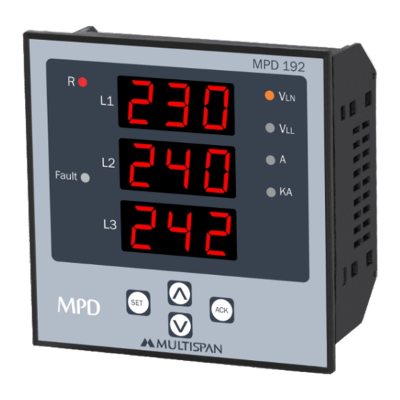
Motor Protection Device
MPD-192
Unbalance
Phase Loss
Lock Rotor Point
Phase Sequence
Neutral Loss
Voltage AC
Voltage AC
30 to 300V(L - N)
50 to 500V(L - L)
< 0.2VA
2.00Amp to 60.0Amp
< 0.2VA
Up to 65A continuous
45.0 to 65.0 Hz
3 Digit, 3 Line 7 Seg 0.56",
RED LED
SET, INC, DEC, ACK
96 (H) X 96 (W) X 52 (D) mm
92 (H) X 92 (W) mm
ACCURACY
Class 1.0 (Standard)
TRIP SETTING:
Under Current
Over Current
Under Voltage
Over Voltage
Over / Under Frequency
Short Circut
Lock Rotor Point
Unbalance
TIME PARAMETER:
Power On Delay
Initial Time Delay
Trip Delay Time
(Voltage, Current, Frequency,
SSP, Unbalance)
Scrolling Time
Reset Time
OUTPUT SPECIFICATION:
Relay
Relay Type
Rating
AUXILIARY SUPPLY:
Supply Voltage
Power Consuption
ENVIRONMENTAL CONDITION:
Working Temperature
Storage Temperature
Relative Humidity
Protection Level
(As Per request)
TERMINAL CONNECTION
20
19
18
17
R
Y
S1
S2
S1
S2
CAT III
NOTE :
USE CT PROVIDED BY MULTISPAN ONLY
Range
Made in India
Current: 2.00A To 60.0A AC
100
~
Voltage (P-P) : 50-500V AC
100-270V AC
!
270V AC
50Hz, 4VA
50Hz,4VA
Relay-1
NO
C
L
N
1
2
3
4
0.00 to 60.0 A
0.00 to 60.0 A
50 to 520V For 3Ø - 3W
30 to 300V For 3Ø - 4W
50 to 550V For 3Ø - 3W
30 to 330V For 3Ø - 4W
45.0 to 65.0 Hz
1 - 9 Scale
0.5 to 9.0 Scale
5 - 60%
0 to 99 Sec
0 to 99 Sec
0 to 999 Sec
1 to 99 Sec
0 to 99 Sec
2 Nos
st
1 Relay ( NO - C - NC )
nd
2 Relay ( NO - C )
st
1 Relay 10Amp, 250V AC
nd
2 Relay 5 Amp, 250V AC
For Resistive load
100 to 270V AC, 50Hz
4VA @ 230 AC MAX
0 to 55°C
0 to 55°C
95 % RH Non-Condensing
IP-65 (Front side As per
IS/IEC 60529 : 2001)
16
15
14
13
12
B
S1
S2
C
NO
Relay-2
System:
3Ph-4W/3Ph-3W
Accuracy Class: 1.0
(P-N) : 30-300V AC
www.multispanindia.com
NC
V
V
V
Y
B
R
5
7
6
8
9
11
N
10
Page 1
Advertisement
Table of Contents

Subscribe to Our Youtube Channel
Related Manuals for MULTISPAN MPD-192


Summary of Contents for MULTISPAN MPD-192
- Page 1 3 Digit, 3 Line 7 Seg 0.56”, Display RED LED Relay-2 Keys SET, INC, DEC, ACK CAT III NOTE : USE CT PROVIDED BY MULTISPAN ONLY DIMENSION: Range System: Made in India Current: 2.00A To 60.0A AC 3Ph-4W/3Ph-3W Size (mm) 96 (H) X 96 (W) X 52 (D) mm Accuracy Class: 1.0...
-
Page 2: Key Operation
Key Operation INSTALLATION GUIDELINES Operator Mode 1. This equipment, being built-in-type, normally becomes a part of main control panel and in such case the terminals To View Individual Parameters Value do not remain accessible to the end user after installation and internal wiring. - Page 3 FAULT MASSAGE Under Current fault Message Phase Loss Message 1) Unc in R Phase 1) R Phase loss Fault in R phase U N C Under Current P H A Phase 2 8 7 R phase Current Value L O S Loss 2) Unc in Y Phase 3) Unc in B Phase...
-
Page 4: Display Pages
5 0 0 Fault WIRING CONNECTION 1) 3 Phase - 4 Wire 2) 3 Phase - 3 Wire NOTE : USE CT PROVIDED BY MULTISPAN ONLY NOTE : USE CT PROVIDED BY MULTISPAN ONLY Relay-2 Relay-2 CAT III CAT III... -
Page 5: Parameter Setting
Password = 19 » Power On Time & ITD Time Selection Password = 39 » Network Selection » Under Current, Over Current, Under Voltage, Over Voltage, Password = 59 » Display Mode Selection (Hold / Scroll) Under Frequency, Over Frequency »... - Page 6 PARAMETER SETTING P A S P A S Enter Password = 29 Enter Password = 29 P A S Enter Password = 39 Press Press S P P C O N Configuration Single Phase Prevention 3 P H 3 Phase E N B (Enable / Disable) (3 Wire / 4 Wire )
-
Page 7: Control Function
CONTROL FUNCTION PARAMETER SETTING Press & P A S R S T Reset Single Phase Prevention (SPP) Together (For Voltage) m O D Mode M A N SPP Time:- 5 Sec Power On:- 5 Sec Manual/Auto/ZVR (Zero Value Reset Time:- 5 Sec Initial Time Delay:- 5 Sec Reset) Press... -
Page 8: Reset Mode
Lock Rotor Point Under Current Lock Rotor Point:- 2.0 Power On:- 5 Sec Power On:- 5 Sec Under Current:- 3.0A Intial Time Delay:- 5 Sec Over Current Value:- 2.0A Lock Rotor Point:- Enable Under Current time:- 5 Sec Initial Time Delay:- 5 Sec Relay Fault:- OFF Over Current:- Diseble Relay Fault:- OFF...
Need help?
Do you have a question about the MPD-192 and is the answer not in the manual?
Questions and answers