
Related Manuals for PEMTECH PT2008


Summary of Contents for PEMTECH PT2008
- Page 1 Gas Detection Technology Model PT2008 Multi-channel Gas Monitor / Controller Revision 2.0 March 2012 Operator’s Manual Pem-Tech, Inc. Houston, Texas U.S.A www.pem-tech.com...
- Page 2 PEM-TECH be liable for special or consequential damages, including, but not limited to, loss of profits or revenue, loss of equipment or down time costs. PT2008 Gas Monitor / Controller Rev 2.0 Page 2...
- Page 3 For this an additional charge may be applicable. NOTE: 1. For all the repairs under warranty, serial number must be legible on the items being repaired. 2. Shipping point is FOB Houston. PT2008 Gas Monitor / Controller Rev 2.0 Page 3...
-
Page 4: Table Of Contents
4.1.1 Change sensor Type 4.1.2 Edit Alarm Levels 4.1.3 Edit Alarm Type 4.1.4 Relay Type 4.2 Program Sensor Location Tags 4.3 Setting MS-Windows for HyperTerminal 5.0 MODBUS Communication Spare Parts List PT2008 Gas Monitor / Controller Rev 2.0 Page 4... -
Page 5: Overview
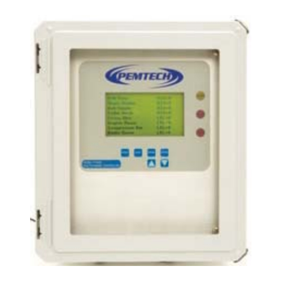
1.0 OVERVIEW Model PT2008 series monitor & controller is designed to monitor and display data for up to 16 remote mounted sensors. The controller features large LCD display, 4 fully programmable alarm relay contacts, and a sensor fault or malfunction relay. Also on the front panel are LEDs for visual alarm indicators. -
Page 6: Data Display
1.1 DATA DISPLAY PT2008 Controller displays location tags and the sensor readings. For controller programmed for more than 8 channels, data is displayed eight channels at a time. Each screen displays data for 10 seconds and then display switched for next 8 channels and so 1.2 FRONT PANEL... -
Page 7: Specifications
1.3 SPECIFICATIONS 1.3.1 DC POWER SUPPLY REQUIREMENTS The standard power requirement for PT2008 controller is 16-28 VDC @ 2 Watts maximum. The DC power is connected to DC terminal on the main connection board. The DC power supplied to this terminal is also routed to the DC power supplied to each of the connected sensor thru a Fuse on the connection board. - Page 8 1.3.5 VISAUL ALARM INDICATORS Amber LED indicator on the front panel for Low / Warn alarm status Red LED for High alarm status Red LED for Sensor Fault / Malfunction PT2008 Gas Monitor / Controller Rev 2.0 Page 8...
-
Page 9: Installation And Startup
2.0 INSTALLATION AND START UP PT2008 series is a wall mount controller. The fiberglass version is rated Nema 4x weatherproof and can be mounted outdoor. The explosion proof enclosure, Nema 7 is suitable for use in hazardous locations. Refer to figure 2 for overall enclosure dimension and mounting holes. -
Page 10: Dc Power Input
Simply remove or pull the screw terminal block from its header base, connect the wires from the sensor and plug it back in. Be sure to check the wires connecting the sensor and Channel Input terminal on the PT2008 connection board are as shown in figure 3 below. -
Page 11: Connection Board
RS232 Figure 4. PT2008 Connection board assembly , layout diagram. Connection board shown is for 16 channels / sensors. PT2008 Gas Monitor / Controller Rev 2.0 Page 11... -
Page 12: Alarm Wiring Diagram
One of Six Relay Outputs Typical Example MALF (FAULT) Relay Wired In Same Manner Load: 5 A Resistive Maximum RLY-x Typical Load LIGHT Screw Terminal Plug-in Blocks Not Shown for Simplicity Figure 5. Typical Alarm Wiring diagram PT2008 Gas Monitor / Controller Rev 2.0 Page 12... -
Page 13: Wiring To Alarm Station
The color of strobe light visually distinguishes between the low toxic and combustible gas alarm. The buzzer or horn is for high alarm for either toxic or combustible. On PT2008 connection board three relays are configured in order to have distinct low alarm for toxic and LEL combustible and a common high alarm (siren) for both toxic and combustible. - Page 14 Gas Reading Strobe / Horn Activated Greater than or Equal to 20 Red Strobe Less than 40 Combustible Red Strobe Greater than or equal to 40 2 & 3 & Horn PT2008 Gas Monitor / Controller Rev 2.0 Page 14...
-
Page 15: Wiring Diagram
2.5.1. Wiring Diagram Figure 6. Wiring PT2008 to Alarm Station PT2008 Gas Monitor / Controller Rev 2.0 Page 15... -
Page 16: Startup
2. Verify that the channel configuration and the sensor connected to that channel input are the same. 3. Verify and change alarm set points according to your specifications. Note: To verify or change alarms or channel configuration refer to monitor configuration section. PT2008 Gas Monitor / Controller Rev 2.0 Page 16... -
Page 17: Normal Operation And Alarms
LED indicators on the front panel should be off. 3.2.2 Alarms PT2008 monitor is equipped with four (4) alarm relay contacts. The monitor activates the alarm relays when any of the sensors exceeds the programmed alarm set point. Also LEDs on the front panel will also light up for visual alarm indication. -
Page 18: Edit Configurations
The data item to be edited must be pointed by an arrow in front of it. Edit the data by using the ENTER, Up & Down arrow keys on the keypad. PT2008 Gas Monitor / Controller Rev 2.0 Page 18... -
Page 19: Edit Alarm Levels
Press the Enter key to toggle between Yes and NO. Select Yes if alarm to be latching, select NO otherwise. Press Down key to jump to next alarm type. PT2008 Gas Monitor / Controller Rev 2.0 Page 19... -
Page 20: Relay Type
When the configuration data for channel 1 is completed press the RESET key to jump to configure channel 2. Configure all the channels. Once all channels have been configured PT2008 will save the configuration into a non- volatile memory and will display the message when finished. -
Page 21: Program Sensor Location Tags
2. Connect the DB9 Male to PT2008 RS232 port and DB9 Female to a laptop’s Serial Comm port. 3. Press and hold the PRGM switch on the front panel of PT2008 until the LCD displays “Program Sensor Location Tags” . Release the switch. - Page 22 PT2008 prompts with message that tag names have been saved. Press “4” key on the keyboard to return to normal operation. PT2008 Controller will now display the new sensor location tags in the first column of the LC display.
-
Page 23: Setting Ms-Windows For Hyperterminal
None 5. Save the current settings by selecting menu option “File – Save As”. Click OK to save the setup. For next time simply click on the “PT2008 Monitor” to recall the settings. PT2008 Gas Monitor / Controller Rev 2.0... -
Page 24: Modbus Communication
5.0 MODBUS Communication MODBUS Registers defined in Model PT2008 Gas Monitor/ Controller. Unit Address: Default address or ID for the Monitor is 120. To change this address perform a MODBUS single write register (Function code 6) to register number 3. Write new address to this register and allow 100 milliseconds before polling with new address. - Page 25 Bit Set if Sensor is currently in calibration mode Bit 3 Not used. Returned as 0 Bit 4 Not used. Returned as 0 Bit 5 - 7 Reserved / Not implemented PT2008 Gas Monitor / Controller Rev 2.0 Page 25...
- Page 26 Table 1. Sensor Numeric Codes: 8 bit Numeric value in MS Byte of the Status Register. Numeric Sensor Type Code Carbon Monoxide Sulfur Dioxide Oxygen Deficiency Hydrogen Nitrogen Dioxide Discrete / Digital Input PT2008 Gas Monitor / Controller Rev 2.0 Page 26...
-
Page 27: Spare Parts List
16 Sensor Connections Connection and relay board assembly for S-51-208 8 Channels / Sensors Connection and relay board assembly for S-51-216 16 Channels / Sensors C-416 4 Amp Buss fuse for sensor power PT2008 Gas Monitor / Controller Rev 2.0 Page 27...
Need help?
Do you have a question about the PT2008 and is the answer not in the manual?
Questions and answers