Table of Contents
Advertisement
Quick Links
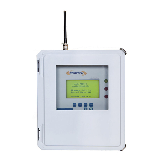
Model PT2008 Series
Remote Annunciator &
Used with:
PT900 Series Control Panel &
PT710 Multi Channel data Transmitter
Pem-Tech, Inc.
Houston, Texas
U.S.A
www.pem-tech.com
PT2008 Remote Annunciator & Data Logger Rev 2.0
Gas Detection Technology
Data Logger
Revision 2
July 2012
Operator's
Manual
Page 1
Advertisement
Table of Contents

Related Manuals for PEMTECH PT2008 Series


Summary of Contents for PEMTECH PT2008 Series
- Page 1 Gas Detection Technology Model PT2008 Series Remote Annunciator & Data Logger Used with: PT900 Series Control Panel & PT710 Multi Channel data Transmitter Revision 2 July 2012 Operator’s Manual Pem-Tech, Inc. Houston, Texas U.S.A www.pem-tech.com PT2008 Remote Annunciator & Data Logger Rev 2.0...
- Page 2 NOTICE PEM-TECH INCORPORATED SHALL NOT BE LIABLE FOR TECHNICAL OR EDITORIAL ERRORS OR OMISSIONS MADE HEREIN, NOR FOR INCIDENTAL OR CONSEQUENTIAL DAMAGES RESULTING FROM THE FURNISHING, PERFORMANCE, OR USE OF THIS MATERIAL LIMITED WARRANTY Pem-Tech, Incorporated warrants all the equipment to be free from defects in workmanship and material.
- Page 3 SERVICE POLICY Pem-Tech has service facility at the factory. For all the repairs contact at our toll free number 1-800- 379-3894 or visit our website www.pem-tech.com For all repairs call us for a Return Material Authorization number (RMA). Inform us briefly the nature of the problem and obtain shipping address.
-
Page 4: Table Of Contents
TABLE OF CONTENTS Overview Data Display Front Panel Keypad switches Installation and Startup Wiring PT2008 Termination Board AC Power Input Connecting RS485 Data Cable Startup Apply Power Initial Setup Normal Operation Data Communication Alarms 2.10 Alarm Reset 2.11 Alarm Bypass / Acknowledge Unit Configuration Set Date &... -
Page 5: Overview
1.0 OVERVIEW Model PT2008 is a Remote Annunciator and Data Logger for alarm and data display of PT900 series Gas Monitor & Controller System. The annunciator/Data Logger is factory programmed to operate in either of two modes: Slave Mode: In this mode the data is transmitted to the annunciator by a remote transmitter model PT710. -
Page 6: Keypad Switches
1.3 KEYPAD SWITCHES RESET: When pressed it will Reset any currently active alarms on PT900 Main Control Panel ACK: Pressing the key will bypass active alarms on PT900 Main Control Panel for 30 minutes. The Bypass message is sent the control module in main control panel. After 30 minutes if any sensor is still in alarm state the alarm relays will be activated again. -
Page 7: Installation And Startup
2.0 INSTALLATION AND START UP PT2008 Annunciator can be mounted direct to the wall or panel. Refer to figure 2 for the size of the enclosure and mounting hole dimensions. The monitor should be installed approximately 5 feet above ground at eye level to view LCD. Avoid installation of the enclosure with LCD facing the direct sunlight. -
Page 8: Wiring Pt2008 Termination Board
2.1 Wiring PT2008 Termination Board. For wiring see figure 3. Also see drawings at the end of this document for wiring with PT900 rack-mount control monitor and PT710 Remote transmitter. Figure 3 shows the termination board of the annunciator. The termination board consists of AC/ DC power supplies , alarm relays and terminal blocks for user connection. -
Page 9: Ac Power Input
2.2 AC POWER INPUT Refer to figure 3. Connect 110/220 VAC power to the Din-Terminals. If only 24VDC power is available simply disconnects DC out wires from the AC/DC Power supply and connect external DC to RED and BLACK terminals next to power supply module. CONNECTING RS485 DATA CABLE RS485 link is used to communicate between the PT900 Series Control Monitors or PT710 Data Transmitter and PT2008 annunciator. -
Page 10: Startup
WARNING Do not run the RS485 cable close to high power lines or areas with high magnetic field. High power lines induce noise into the data cable which may distort the communication between the monitor and the annunciator. 2.4 START UP Complete the following procedure for the normal operation. -
Page 11: Normal Operation
2.7 NORMAL OPERATION The annunciator continuously collects data from the Gas Monitor via RS485 serial communication and displays the gas readings and currently active alarms, if any. Figure 4 below is an example of the data displayed by the annunciator. Remember that the sensor tag or location names in the left column of the LC display are programmable. -
Page 12: Data Communication
Display Screen during alarm conditions **** ALARMS ****** Indicates the Mud Pit H2S sensor Mud Pit H2S = 15 and Shale Shake LEL sensor are in Shale Skakr LEL = 30 alarm conditions. Figure 4(b). Data Display on the LCD (Alarms Active) 2.8 DATA COMMUNICATION The annunciator continuously collects data from all control modules in PT900 series gas monitors. -
Page 13: Alarms
2.9 ALARMS There are three (3) dry alarm relay contacts provided each rated at 5 Amps. Relay 1 and Relay 3 are pre-wired at the factory to an internal buzzer for local audible alarm. However, the buzzer can be disconnected and these relays can be used for External Audible and visual Alarm Devices. -
Page 14: Alarm Bypass / Acknowledge
2.11 ALARM BYPASS / ACKNOWLEDGE When the “ACK )” key on the front panel is pressed the unit will send an alarm (nowledge bypass command to all the control modules that are currently in alarm state to deactivate the relays and set them in bypass mode for next 30 minutes. Thus the alarm will not be activated by the control modules / sensors for 30 minutes. -
Page 15: Unit Configuration
3.0 UNIT CONFIGURATION This option allows to change system parameters such as data and time for data logging, number of channels or control modules installed in the PT900 main control panel. Press and hold the PRGM key until the following menu options are displayed on the LCD. Set Date &... -
Page 16: Print Historical Event Log
3.2 PRINT EVENT LOG Note: Before printing the event log refer to section 3.6 on HyperTerminal Setup for data download and save the historical records to a laptop computer. Data is downloaded using the serial port connection. The laptop computer must therefore be equipped to accept serial data from the controller. - Page 17 2. Direct Data Download This method simply requires that the cable is connected while unit is in normal operation. The 4 pin Plug of RS232 cable when connected to the receptacle on the annunciator the “cable connect signal” is detected and the unit automatically goes into Print Event Log mode.
- Page 18 Following is a sample Event Log Report Event Log Report Report Date: 08/24/12 15:14 Page: 1 Location: _______________________ Date/Time Ch# Tag Event Desc -------------------------------------------------------------------------------------------------- 08/22/12 12:19:28 01 Drill Floor - Calib Mode 08/22/12 12:19:08 02 Shale Shaker - Alarm 1 Active H2S= 10 08/22/12 12:18:49 03 Channel 3 - Bypass Active H2S=...
-
Page 19: Erase Event Log
ERASE EVENT LOG Selecting this option will reinitialize the entire log record archive in the memory. The command cannot be cancelled once selected. This may take up to 15 minutes to clear the entire memory of old data log records. The system will display the % completion progress. Returns to previous menu once completed. - Page 20 4. If the Hyper Terminal is set and connection has been made properly a small menu will be displayed on the laptop screen by the annunciator. 5. If nothing appears on the laptop screen check if Hyper Terminal is configured properly and cable is connected.
- Page 21 When all the tag names have been entered press the escape key to display the menu options. To change the number of active channel in the Main control panel press the “3” key and enter and the number of active channels / tags. Select option 2 (“Change Location Tag”) to enter the new location tag name.
-
Page 22: Setting Windows Hyper Terminal For Data Download
3.6 Setting MS-Windows Hyper Terminal for Data Download & Edit Sensor Location Tags 1. Open Hyper Terminal program in Windows “Programs - Accessories - Communication” folder. 2. If you are setting up first time then click on File – Open New Connection. Supply a new “New Connection”... - Page 23 PT2008 Remote Annunciator & Data Logger Rev 2.0 Page 23...
Need help?
Do you have a question about the PT2008 Series and is the answer not in the manual?
Questions and answers