
Related Manuals for PEMTECH PT2008


Summary of Contents for PEMTECH PT2008
- Page 1 Gas Detection Technology Wireless Gas Detection PT2008 Monitor & Controller Revision 4 October 2015 Operator’s Manual (ISM 2.4 GHz & 900 MHz) Pem-Tech, Inc. Houston, Texas U.S.A www.pem-tech.com...
- Page 2 NOTICE PEM-TECH INCORPORATED SHALL NOT BE LIABLE FOR TECHNICAL OR EDITORIAL ERRORS OR OMISSIONS MADE HEREIN, NOR FOR INCIDENTAL OR CONSEQUENTIAL DAMAGES RESULTING FROM THE FURNISHING, PERFORMANCE, OR USE OF THIS MATERIAL LIMITED WARRANTY Pem-Tech, Incorporated warrants all the equipment to be free from defects in workmanship and material. The products will operate in conformance with the published specifications when subjected to intended and proper usage for the period of one (1) year from the date of shipment.
-
Page 3: Table Of Contents
TABLE OF CONTENTS 1.0 Step by step installation guide Enclosure mounting and dimensions Power and Alarm Connection to PT2008 1.1 Overview 1.2 Data Display 1.3 Front Panel 1.3.1 Keypad Switches 1.4 Specifications 2.0 Installation and Startup 2.1 Connection Board assembly 2.2 AC Power Input... -
Page 4: Step By Step Installation Guide
1.0 Step by Step Installation Guide Install PT2008 Monitor to a wall or panel using 4 of the mounting bracket provided. See figure 1 for mounting holes and enclosure dimensions. Install the Dipole Antenna on top of the enclosure. If external high gain antenna is installed then connect using coax cable with surge arrestor. -
Page 5: Enclosure Mounting And Dimensions
Figure 1. Fiberglass enclosure, dimensional overview Wireless Gas Detection Page 5... -
Page 6: Power And Alarm Connection To Pt2008
RS232 Figure 2. Connection & Terminal layout inside PT2008 Controller Wireless Gas Detection Page 6... -
Page 7: Overview
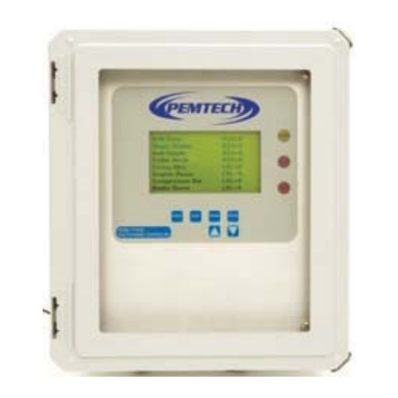
1.1 OVERVIEW Model PT2008 series “Wireless” monitor & controller is designed to monitor and display data from remote mounted Ultra 1000 Series (wireless) sensors (toxic and Combustibles). Controller can communicate with up to 24 detectors on the wireless network. The controller features a large LCD display, 6 fully programmable alarm relay contacts, and a communication or sensor fault relay. -
Page 8: Data Display
1.2 DATA DISPLAY PT2008 Controller displays sensor location tags ( or default channel numbers) and the sensor readings. For controller configured for more than 8 wireless detectors , data is displayed eight channels at a time. Each screen displays data for 10 seconds and then display is switched for next 8 channels and so on. -
Page 9: Specifications
SPECIFICATIONS Radio Module: 900 MHz 2.4 GHz Sensitivity -110 dBm -105 dBm FHSS (frequency Hopping Spread Frequency Hopping, wide band Spread Spectrum spectrum modulator Data Encryption 256-Bit AES Encryption FCC Part 15.247 USA FCC Part 15.247 Certification 4214A 1208 Canada 4214A 1208 Canada ETSI Europe Up to 5 miles (8 Km) -
Page 10: Installation And Startup
2.0 INSTALLATION AND START UP PT2008 series is a wall mount controller. The enclosure is rated Nema 4x weatherproof and can be mounted outdoors. Refer to figure 1 for overall enclosure dimension and mounting holes. The mounting feet for the fiberglass enclosure are provided separately. -
Page 11: Wiring To Alarm Station
2.4 WIRING TO ALARM STATION (Typical for Toxic and Combustible) Figure 4 shows a sample wiring diagram to connect PT2008 alarm relays to an Alarm Station. The typical alarm station consists of 2 distinct color strobe light and a buzzer or siren. - Page 12 Relay # Sensor Gas Reading Strobe / Horn Activated Greater than or Equal to 10 Amber Strobe Toxic Less than 15 (H2S, CO, NO, NO2, SO2, Amber Strobe Etc. ) Greater than or equal to 15 1 & 3 & Horn Relay # Sensor Gas Reading...
- Page 13 ALARM 5 ALARM 6 RETURN High Tox/LEL Low LEL LOW Toxic ALARM 3 ALARM 4 ALARM 2 ALARM 1 BREAKER DC IN Supply Return Supply Return Supply Return Figure 4. Wiring PT2008 to Alarm Station Wireless Gas Detection Page 13...
- Page 14 Wiring Alarm Station using external Power Figure 4A. Wiring PT2008 to Alarm Station Wireless Gas Detection Page 14...
-
Page 15: Startup
3.2.2 Alarms PT2008 monitor is equipped with four (4) alarm relay contacts. The monitor activates the alarm relays when any of the sensors exceeds the programmed alarm set point. Also, the LEDs on the front panel will also light up for visual alarm indication. -
Page 16: Alarm Reset
3.2.3 Alarm Reset Once the gas concentration has dropped below the alarm setpoint the relay will deactivate itself. However, this will occur only if the relay is configured as non-latching (NL). If the relay is configured latching then it must be deactivated manually. To deactivate the latching alarm simply press and hold RESET switch on the front panel for few seconds. -
Page 17: Edit System Configurations
4.0 Edit System Configuration To modify system configuration or parameters press and hold the “PGRM” key and the following configuration menu is displayed. Use the ▲ and ▼ keys to move the arrow to select the option and press ENTER key. Edit Configuration . -
Page 18: Set Alarm Levels
*** Select to Edit Alarms **** *** Edit H2S Alarms *** H2S Level Relay AL.1 10 AL.2 AL.3 AL.4 Exit AL.5 AL.6 *** Select to Edit Alarms **** *** Edit LEL Alarms *** Level Relay LEL AL.1 20 AL.2 AL.3 Exit... -
Page 19: Alarm Relay Types
4.2 Alarm Relay Type This option allows the user to select the alarm relays to be Latching or Non-Latching type. Also if the relays to function as Normally Energized or De-Energized mode. Select Relay Type from the edit configuration option list and the following screen is displayed. **** Relay Type *** R #1 ... -
Page 20: Enable / Disable Channel
The above configuration illustrates that channel / detector with address 13 thru 16 have been disabled, thus making the unit as a 12 channel controller. PT2008 will only display data from 12 detectors on the network. If any additional detectors are installed then simply enable the channel. -
Page 21: Sensor Location Tags
1. Start the Hyper Terminal program on the laptop computer as explained in the next section. 2. Connect RS232 port on PT2008 to Serial Comm Port on laptop using standard DB9 Male-Female RS232 cable. 3. From main configuration menu select “Program Location Tags” option and the press ENTER key. - Page 22 • PT2008 prompts with message that tag names have been saved. • Press “4” key on the keyboard to return to normal operation. PT2008 Controller will now display the new sensor location tags in the first column of the LC display.
-
Page 23: Setting Ms-Windows Hyper Terminal
Flow Control None 5. Save the current settings by selecting menu option “File – Save As”. Click OK to save the setup. For next time simply click on the “PT2008 Monitor” to recall the settings. Wireless Gas Detection Page 23... -
Page 24: Network / Zone Id
Network / Zone ID is used to avoid the cross talk between multiple sensors and controllers. Cross talk happens if multiple PT2008 Controllers are used within short distance to each other and sensors. A controller and all the associated sensors must have the same network ID in order to communicate properly. -
Page 25: Communication To Plc
Modbus RTU is a standard protocol for communication between a PLC / Controller and slave devices. This section briefly explains the communication with PT2008 Controller through Modbus RTU protocol. Only the PLC / Controller can make requests to read the contents of the data registers in the controller. - Page 26 400001 thru 400010 - System Status and misc. housekeeping registers 400001 System “Heart Beat” register Unsigned 16 bit integer value This register is increment once every second (approximately) The maximum value is 65535 after which it rolls over to 0 400002 Inter-processor communication failure Integer value 0 or 1...
-
Page 27: Modbus Register List / Map
MODBUS Register List Each sensor has 4 MODBUS register block. Register for the sensor are sequential. First register is for current gas reading, second register has sensor status and diagnostics bit map, third is register holding data for the battery voltage. Fourth register is used internally and should not be read by the user’s PLC . - Page 28 Status Bit Map Register This is a 16 bit integer register. Each bit / byte is used for sensor status and diagnostic information. The MSByte ( Most Significant 8 bits) of this register contains the sensor type code as listed in table 2. The LSByte ( Least Significant 8 bits) defines the status of sensor as shown in the data frame below.
- Page 29 Table 2. Sensor Codes: Code Sensor Type Carbon Monoxide Sulfur Dioxide Oxygen Deficiency Hydrogen Nitrogen Dioxide Discrete / Digital Input Hydrogen Fluoride Wireless Gas Detection Page 29...
-
Page 30: Spare Parts List
Spare Parts List Part Number Description 900 MHz 2.4 GHz 61-501-09 61-501-24 Main CPU Board Assembly with LCD Display 61-512-09 61-512-24 Connection, Relay Board assembly with Radio Module C-1026 110/220 VAC to 24 VDC power Supply Antenna, Coax Cables and Accessories Part Number Description 900 MHz...
Need help?
Do you have a question about the PT2008 and is the answer not in the manual?
Questions and answers