
Related Manuals for PEMTECH PT920-16SS


Summary of Contents for PEMTECH PT920-16SS
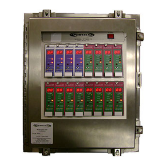
- Page 1 MODEL PT920-16SS 16 CHANNEL GAS MONITOR & CONTROLLER Operator’s Manual Revision 2.0 May 2008 Pem-Tech, Inc. Houston, Texas U.S.A.
- Page 2 NOTICE PEM-TECH INCORPORATED SHALL NOT BE LIABLE FOR TECHNICAL OR EDITORIAL ERRORS OR OMISSIONS MADE HEREIN, NOR FOR INCIDENTAL OR CONSEQUENTIAL DAMAGES RESULTING FROM THE FURNISHING, PERFORMANCE, OR USE OF THIS MATERIAL LIMITED WARRANTY Pem-Tech, Incorporated warrants all the equipment to be free from defects in workmanship and material.
- Page 3 SERVICE POLICY Pem-Tech has service facility at the factory. For all the repairs contact at our toll free number 1-800-379-3894 or visit our website www.pem- tech.com For all repairs call us for a Return Material Authorization number (RMA). Inform us briefly the nature of the problem and obtain shipping address. Properly pack the equipment before shipping.
-
Page 4: Table Of Contents
Specifications for Model PT920 Series Control monitor Overview Programmable Relays Figure 1. PT920 Control module Front Panel diagram Installation and Startup Figure 2. PT920-16SS Enclosure dimension AC / DC Unit Power Up Figure 3. System Overview drawing, User termination, control modules in Rack assembly... -
Page 5: Specifications
SPECIFICATIONS For PT920 Rack Assembly with Power Supply MOUNTING: Wall or Panel Mount ENCLOSURE: NEMA 4X Stainless Steel Enclosure with clear window DIMENSIONS: 19”H x 16”W x 8”D WEIGHT: 45 Lbs. -40 °F to +170 °F. (-20 °C to +70 °C.) OPERATING TEMPERATURE POWER INPUT:... -
Page 6: Specifications For Model Pt920 Series Control Monitor
SPECIFICATIONS For PT920 Control Module Display Range: 0 to 99 for Toxic and Combustibles 0 to 25.0 % for Oxygen deficiency ( 3 Digit Display) Input Signal: 4-20mA ( for Gas Control Module) Discrete ( For Status Input Module) Relay Ratings: 4 each Form C type relay contacts Rated 5 Amps each Low, High, High-High, and Malfunction... -
Page 7: Overview
OVERVIEW Pem-Tech model PT920 is a microprocessor based single channel monitor that utilizes the latest digital design techniques in instrumentation. The monitor uses an 8-bit high speed RISC processor with a highly accurate analog to digital logic. The controller module receives the signal from remote gas transmitters and displays the gas concentration. - Page 8 THUMB SCREW MODEL PT 920 DIGITAL DISPLAY HIGH LEDs FOR VISUAL ALARM INDICATION HI−HI MALF PUSHBUTTON SWITCH FOR ALARM RESET RESET NORMAL ALARMS BYPASS TOGGLE SWITCH FOR ALARM BYPASS HOUSTON, TX MODULE HANDLE Figure 1: PT920 Series Control Module...
-
Page 9: Installation And Startup
INSTALLATION AND START UP PT920 Enclosure must be installed in a safe area. Figure 2 shows the mounting holes for the stainless steel enclsoure Main control rack assembly can hold up to sixteen (16) PT920 series control modules. On the front panel of each module a captive screw is provided to secure the module to the rack. -
Page 10: Ac / Dc Unit Power Up
AC / DC Power Up AC Power Input If an AC/DC Power supply is installed in the unit then Din-Terminals are installed on the lower left corner of the Main connection board for the main AC line input. The connections on the Din-terminal blocks are labeled L N G. - Page 11 POW ER ALARM RESET AC PO W ER SW ITCH M ASTER ALARM (IF AC PO W ER SUPPLY R ESET SW ITCH INSTALLED) HO USTO N, TEXAS G AS M ON ITOR M OD EL PT920−16 CHANNEL 1 CHANNEL 2 C HANN EL 3 CHANN EL 4 CHANNEL 5...
-
Page 12: Connecting Sensors To Monitor
Connecting Sensors to the Monitor Connecting 4-20mA Transmitter (Gas Sensors) (Toxic or LEL Combustible Control Modules) Three (3) pin screw type terminals are provided on the main connection board for remote sensor connection. The terminals are labeled as CH-1 thru CH-16 and each pin is identified as +, - , & E for sensor DC supply, ground, and 4-20mA input signal respectively. -
Page 13: Connecting Proximity Sensors
Connecting Proximity Sensors (Contact switches) (Status Input Modules) For proximity sensors or contact switches only 2-wire connections are + & E needed. Simply connect terminal pins to the proximity sensors. CAUTION ! Do not connect “-“ terminal to the sensor as it may blow the fuse on the control module CAUTION ! PROXIMITY SENSOR... - Page 14 DC−IN Figure 6. PT920 Connection Board. Typical 4-20mA sensor connection...
- Page 15 Auxiliary 10-Amp Alarm Relay Board The auxiliary relays interface board is located in lower right corner of the main termination board. See figure 7 for wiring details of the relay board to the main PT920 connection board. There are 4 relay contacts on the relay board assembly (Alarm 1 thru Alarm 4).
- Page 16 RST/ACK DC−OUT RELAY−OUT RELAY PWR RS485 HI−HI FAULT DC−IN Figure 8. Jumpers to configure control modules as TOXIC and LEL for proper alarm relay activation on the Aux Relay Board Assembly.
-
Page 17: Wiring Audio / Visual Alarms
Wiring Audio / Visual Alarms Figure 9 shows a typical wiring diagram for connecting alarm devices to an Auxiliary Relay board assembly. Each relay on the auxiliary board is activated by the control module. Note that contacts are dry or potential free. -
Page 18: Startup
Start Up Follow the instructions below for normal unit operation. 1. Complete the mounting and wiring procedures described in earlier sections. 2. Follow gas sensor & transmitter operation manual for proper wiring of sensors with the monitor. 3. Verify all the wiring connections to be correct and secure. 4. -
Page 19: Setting Control Module Id / Address
Setting Control Module Address / ID ***** Skip this section if RS485 or Remote annunciator are not used ****** Each PT920 control module must have a unique address for RS485 communication with the remote annunciator. Control modules must be addressed 1 thru 16. The current module address is flashed for few seconds during upon startup. -
Page 20: Normal Operation And Alarms
NORMAL OPERATION AND ALARMS Each Control module on the main control panel has push button switch for Alarm Reset or Adjust and an Alarm Bypass toggle switch. Also 2 digit bright display and LED indicators for visual alarms. Gas Control Modules – For Gas Sensors / 4-20mA Transmitters During normal operation the toggle switch on the module front panel must in NORMAL position. -
Page 21: Alarms
Alarms Each PT920 control module is equipped with four (4) alarm relays. The relays are used to activate relays on the main connection board. The control module activates the alarm relays when the sensor reading exceeds the programmed alarm set point. Also LEDs on the front panel of the control module will also light up for visual alarm indication. -
Page 22: Alarm Bypass
Alarm Bypass When the control module is in alarm Bypass mode all the relays on the module are inhibited. The relays will not be activated. However, the visual alarm LED indicators will be functioning and flash once every seconds if the gas reading exceeds the alarm level. Furthermore, the LED display will also flash once every second. -
Page 23: Programming Alarm Levels
Programming Alarm Levels 1. Move the toggle switch on the front panel to BYPASS position. 2. Press and hold the pushbutton switch (above the toggle switch) until the Low alarm LED starts flashing. Release the switch. 3. While the LED is flashing the display will show the current alarm level. -
Page 24: Setting Alarms As Latching Or Non-Latching
Setting Alarm as Latching or Non-Latching The alarms can be set as latching or Non-Latching by setting the Dip- Switch located on lower left corner of the control module. See figure 5. The dip-switch is labeled as Relays with arrow indicating the switch selection for latching or non-latching. - Page 25 Figure 10. PT920 Control Module...
-
Page 26: Malfunction Condition
Malfunction Condition The malfunction alarm is activated when the 4-20ma analog output from the sensor transmitter falls below 2.0mA. This is caused if the sensor requires calibration. The malfunction also occurs if wires connecting the sensors are broken. The fault relay is always non-latching and has a common alarm contacts on the main connection board. -
Page 27: Parts List
Parts List Part Number Description C- 480 Replacement card guide C-127 Mini Sensor Fuse PT920 Series Control Modules PT920-H Model PT920 Control Module for H2S sensor PT920-L Model PT920 Control Module for LEL sensor PT920-OXY Model PT920 Control Module for oxygen sensor PT920-SO2 Model PT920 Control Module for SO2 sensor PT920-IM...
Need help?
Do you have a question about the PT920-16SS and is the answer not in the manual?
Questions and answers